
What is Arsigdec
ArSigDec is an Arduino sketch that acts as a DCC signal decoder for all led-based signals.
You can create all led signals with a maximum of 8 leds and 10 aspects per signal.
It also contains a database with 50 pre-configured signals of some European countries.
Including the Netherlands, Germany, Belgium, Austria, Switzerland, Spain, France and United Kingdom
Two modes of operation
ARSIGDEC runs in two different modes. A configure mode and a run time mode. (aka normal mode)
In configure mode you configure the signals that you want to use.
The Arduino is connected via USB to your computer. With only your keyboard and monitor you can easily, with a simple question and answer ‘game’, specify all the settings that you want for your signals. Therefore ARSIGDEC uses one-character commands. See the manual for examples. It communicates with you by using a terminal emulator program called Putty.
No complex puzzling with CV’s!
With the E-command (Exit) you change to run time mode.
In run time mode ARSIGDEC ‘listens’ to the DCC signals on your track.
If an address passes by that you have configured for one of the signals, ARSIGDEC will set the signal according its configuration.
All ARSIGDEC features one by one:
- Controlling a maximum of 8 signals per UNO or 30 on MEGA
or - Controlling 16 leds per UNO or 65 on MEGA
- A signal may contain upto 8 leds. Parallel connected leds count for one led.
- A signal can have upto 10 different aspects
- A signal can be configured manually. You can specify for each aspect and for each led its action: on , off or flashing.
In this way you can configure almost all signals in the world. - Support of Dutch ‘P-signals’ (red-green change with automatic intermediate yellow)
- Contains a database with the most important signals. You don’t need to configure these signals.
Just select a signal number from the database. - Configurable on/off times when flashing.
- Configurable on/off fading time per signal.
- Configurable maximum brightness per led.
- Suitable for signals with common anode and common cathode.
- Interactive, via screen and keyboard, configuring of the signals. That is independant of your DCC Command station and requires no puzzling with complex CV’s.
- No need to use the Arduino IDE (development environment)
- Assign a random DCC base address (1-2000) for each signal.
- One(1) DCC address controls two different aspects.
Subsequent addresses are used for more aspects. - A test option. All signals are showed
- A documentation option shows all settings.
- Assign an alpha numeric administrative code to a signal
- A reset option that clears all settings from memory.
- Option to correct the address offset of a Roco Command station (MM, z/Z21)
- A help options shows all commands.
- A log option in which all configuration sessions are saved.
- Independant of used bus structure (S88, LocoNet, XpressNet)
But in operation mode it uses only DCC
Hardware requirement:
The standard DCC signal can’t be used directly to an Arduino.
Therefore you need a DCC decoder. This DCC decoder converts the DCC signal to a signal that can be applied to an Arduino.
Arcomora has two options for such a DCC decoder.
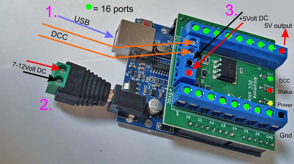
A DCC shield on top of an Arduino UNO or Arduino MEGA. (Arduino not included)
Can be powered:
– via USB
– Arduino jackplug 7-12 Volt
Screw-to-jack plug included!
– External 5V to screw terminal
Indicator leds for power, status and DCC
SMD print, only solder terminals and Dupont pins.
Price: €7,95
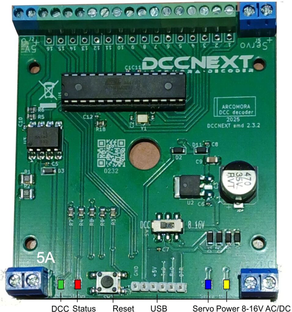
You can also use the DCCNext. The DCCNext combines an Arduino and the DCC shield on a single pcb. A separate Arduino is no longer required.
To date I’ve used the software only. It’s easy to use and saved lots of time due to being able to mix types of signals on just one board. I’m using two head and three head searchlight signals both in common anode and common cathode configurations. Up until now I’ve kept each type on it’s own board but no longer.
Looking forward to using the shield components and boards.
Ted
Is one able to use the ArLoco sheild to interface with ArSigDec (or for that matter the MarDec) ? This would enable DCC signals to come from Loconet rather than the track.
I see that some work would be required as the input pins are different.
I ask because although I’m happy to use the DCC signal from the track on my home layout, we don’t allow that on the club modular layout that gets very large at times and (rightly or wrongly) we don’t want to interfere with the track signal.
Thanks, Ted
Hi Ted,
No, you can’t use the ArLoco for that.
You can use the LocoNet-B connector of the command station or booster and connect both outer wires 1 and 6 to the DCC input of Mardec/Arsigdec.
Hello,,
I have been using Mardec to control servos for my turnouts and now considering Arsigdec to control signals.
I am considering Simple 3 light signals (Green Amber and Red) to be control which is available in Aliexpress, it has 4 wires 1 black and Yellow Green and Red for the respective leds.
My question is, do I really need to use the Shield you mentioned in the website as I already developed the function Decoder that is being used for Mardec, Can I use the same circuit or do I need to create a separate one for Arsigdec.
If I use Arduino Mega then should how many signals it will control
Thanks for great work
I would highly recommend to develop some videos for this great work as people of not fully aware.
First
Hi Farhan,
What you basically need is a DCC circuit as described in the manual. You can use one circuit for multiple Arduino’s. But the DCC shield that I offer is easier to use but has no option to connect the output to another Arduino.
On a MEGA however the shield is mandatory.
A MEGA can control up to 59 leds in total. So for 3 led signals you can control 19 signals.
Nico
Hallo Nico,
ich habe diesen Kommentar leider erst gelesen, als ich bereits die Komponenten für die DCC Schaltung gekauft und verbaut habe.
Können Sie mir sagen, warum das mit dem Mega nur mit dem dcc shield funktioniert? Grundsätzlich wird doch genauso das DCC Signal an einem Pin benötigt. Ist dies ein anderer als Pin D2?
Ich stehe nun vor der Entscheidung den DCC shield oder einen Uno einzusetzen beides leider erst nach Lieferzeit möglich… Schade.
Ansonsten tolles Projekt!
Hallo Bahne,
The shield covers pin 17 of the Mega. To prevent confusion this pin is disabled by default in the software.
That does not mean that a shield is mandatory; but keep in mind that pin 17 can’t be used.
So you van use your own DCC-circuit.
Nico
Nico,
As pin 17 is not used only 58 Leds will workwith a Mega.
Hi Donald,
You’re right. On a MEGA you can use 59-port17=58 leds.
Nico
bonjour, existe-t-il une version en français du document “iTrain en Arsigdec.pdf”
merci
hallo, is er een franse versie van het document “iTrain en Arsigdec.pdf”
Dankjewel
Hi Frederic,
No here is no French version.
But I can send you the Dutch version in MS-Word format. You can translate it yourslf with translate.google.com or deepl.com
Nico
Hallo, ik werk met een arduino mega, arsigdec is daar geïnstalleerd, heb je nog een decoder (ex uno) nodig om de naaldspoel en servo aan te drijven met een extra kaart PCA9685 of kunnen we alles doen met de mega
Dankjewel
Frederic
Hallo Frederic,
De Arsigdec is alleen voor lichtseinen. Voor armseinen heb je Mardec nodig om met een servo de arm te bewegen.
De PCA9685 wordt niet ondersteund door Arcomora.
Nico
Tout fonctionne parfaitement une fois la centrale bien configurée.
Le logiciel est en anglais mais très simple d’utilisation. Un pas à pas très intuitif.
Avec un mega, je contrôle 4 signaux à 2 feux et 17 signaux à 3 feux.
Merci pour le support en ligne par mail qui est excellent.
Je recommande vivement ce système.
Christophe
Merci Christophe
Hi. Am using the shield and ArSigDec with MEGA to control 15 signals with 3 LEDs on each. Works like a charm along with Digikeijs DR5000 and iTrain automation software!
This is the way to go if signals need to be controlled.
In case something doesn’t work, it’s 100% sure that it’s a user fault and not a problem with the shield or the sketch.
Special thanks to Nico for support par excellence and the hand holding he did to get me up & running with my first Arduino project. Must appreciate the support he provided!
Hi Shailesh,
Thanks for your kind words.
Nico
Hi Nico, the mardec , shields and arsigdec boards work and test fine when configuring. I use DCC ++ with JMRI for my base station. I entered the address I chose for my servo in my base station for mardec and it works perfect when commanded with DCC. With the arsigdec I chose 100 for my base address with 3 leds and 5 aspects. Aspect 1: oxx, on address 100-R/0, Aspect 2: xox, on address 100-G/1. How would separate addresses and aspects with the same base number 100, be entered into a base station that will only accept numbers and not characters or letters, my base does not recognize 100-R/0 or 100-G/1 as a legitamate address. Is there a way to convert these into recognizable addresses for NMRA standards? Thank you, Dave.
Hi David,
The addition -G/1 and -R/0 are NOT part of the address. Each address controls 2 aspects.
The first aspect uses the Green button on a command station and has a bitvalue 0 (zero)
The second aspect uses the Red button and has a bitvalue of 1 (one)
That’s all.
Nico
Is there also a support for multiple PWM drivers PCA9685?
Uli
Sorry Uli. The PCA9685 is not supported
Nico
First off, thank you for providing these great programs to the community.
I plan to use a sensor shield with its own power supply and an external DCC decoder circuit on a Mega.
Since there are several pins on the Mega reassigned or disabled, would it be possible to get a pin-assignment of used channels on the Mega?
Hi,
Mardec does not use the additional pins on a MEGA.
Arsigdec and ArLoco do use the additional pins on a MEGA.
For an Arsigdec on a MEGA applies:
On a MEGA applies:
Ports 1 to 16 are connected to the screw terminals
Ports 18 to 53 are connected to pins 18 to 53.
Ports 54 to 59 are connected to A10 to A15.
Pin 17 is NOT used on the MEGA.
For the ArLoco on a MEGA see the ArLoco manual
Thank you
Ik gebruik Arsigdec op mijn baan voor het aansturen van alle lichtseinen op mijn baan Duitsland tijdperk 3. Er hangen nu 8 Nano’s onder met seinen van Viessmann. Ik heb de weerstanden niet verwijderd van de seinen en met een helderheid van 100% hebben de seinen de juiste lichtsterkte. Verder een trafotje gekocht van 5 volt die de Nano’s van stroom voorziet. Erg tevreden met het resultaat.
is it possible tor run mardec on arduino nano? it tells me not enough memory.
Hi James,
Yes you can. But you must first put a new bootloader on it.
See the document on how to do this on my download page.
https://www.arcomora.com/wp-content/uploads/2021/08/flash_bootloader.pdf
I have successfully installed ArSigDec on an Arduino Pro Mini, and I am using Geoff Bunza’s 3PJ decoder board which provides the DCC interface and can supply power to the Pro Mini either from a separate DC source or from the DCC connection (like the DCC/Powershield). I am using this setup where space is restricted or low-density installs where I don’t need the full set of output pins. It’s working great so far with both N and HO scale signals!
You are also not limited to the 150mA output of the Pro Mini regulator. I’ve installed a 250mA regulator on mine, but you can install higher output regulators if required.
Thanks again, to Nico and everyone for all the great work! Cheers!
Hi Nico,
I’ve started to configure my first DCCNext with Arsigdec. Everything is running fine so far.
I’m using common anode and common cathode on separate modules, as I understood, from the configuration instructions, that I have to choose upfront which type to use. However, reading further the manual I also got the impression that, if after programing all the signals, we go and modify just one (‘M’ command), we should be able to change if it’s common anode or common cathode. Is this so? I mean, can we have both types of signals on the same DCCNext module?
Thanks.
Kind regards,
António
Yes, You can set the polarisation of each individual signal by using the M command.
The generic setting applies only to new added signals.
Nico
OK, thanks.
That’s good news!
KR,
António
Hi Nico, I am still very satisfied with your solutions. Working perfectly. Actually I am missing a dark mode feature. Meaning that the leds will be dimmed with x% , I will use this feature the moment the trains are running after “sunset “. Do you have any plans for an update.?
If not, I need to add extra hardware, e.g. relais with will add an extra resistor in the common line of the leds.( a little ruthless way, no real running).
Hi Nico,
Is it possible to configure the signals in such a way that the actual leds on are first faded to off and then the new leds go on afterwards? So that there is a gap of a few milliseconds (100ms for example) between two aspects in which all leds are off.
Sorry, that is not possible.
Nico
Good morning, Sir,
I have a problem with Argisidec which is that, everything is wired on the shield card and on a Mega, the test lights work. but when I exit the program and I test with Rocrail nothing happens. The Mega is connected to 5V, the shield card is connected to the DCC bus, and the USB cable is removed in operating mode. Can I have your help please?
Sincerely
Alain LIBBRECHT
Hi Alain,
Mosty likely this is an addressing issue.
Try this tool: https://www.arcomora.com/wp-content/uploads/2023/04/NmraTransformer.exe
See this document: https://www.globalvisuals.nl/downloads/ArsigdecRocRailUK.pdf
More info: https://wiki.rocrail.net/doku.php?id=addressing:accessory-pg-en
There is no reason to remove the USB cable.
Nico
Hello Nico, I use only Linux on my laptops. Can I still use the excellent ‘question and answer’ setup ‘game’ for ArSigDec?
Thank you very much,
Tim Jones
Download MacLinux.zip from downloadsite. It contains files for a terminal emulator including instructions
Bonjour,
Question de néophyte : Comment fait on pour connecter 2 ARSIDEC (ou 2 MARDEC) ensembles sur un même circuit ferroviaire ?
Strange question. Connect each module, DCC-shield or DCCNext, to the DCC signal from the track. You can also place a wire from one module to another.
Hi Nico, good morning,
I’m experiencing a strange phenomena with the ArSigDec and DCCNEXT signal control.
I’ve configured the DCCNEXT decoders (I have 3) with the signal setup I want and everything was working fine, but recently, for some reason, when I startup my layout the signals do not lit. If I connect back the laptop and test the signals (with the ArSigDec SW), then everything gets back to normal operation. However, the next time I restart my layout, the signals do not lit again.
Any idea of what might be happening?
For control I’m using a Märklin CS2 with Rocrail.
Thanks in advance for your support.
Best regards,
António
Hi Nico! Is it possible to use ArSigDec to drive a crossing signal (two LEDs which flash alternately)? I can see how to make both LEDs flash, but not alternate on/off. Perhaps I need a dedicated flasher circuit. Thanks!
Use Mardec for that. Connect two leds anti-parallel to a single port and use mode 1 (flashing, with equal on/off time).
See also big picture in Mardec manual.
Hello I would like to know where to bye the ARCOMORA or the ARSIDEC ?
Hardware: http://www.arcomora.com/order
Software: http://www.arcomora.com/download
Will you include DCCext support at some point time?
As that can save up on DCC addresses for complex signals as you can use 1 address with many aspects.
No, I do not have that intention.
Sorry Hugo