
Arcomora offers a full range of products for LocoNet:
ArLoco/Power shield: SOLD OUT, No longer available
LocoNext: a new SMD module for encoding/decoding LocoNet signals
Okkie8: SOLD OUT, No longer available
OkkieNext4x4: a SMD module with 16 channels for current detection and four Common lines
Combi package: LocoNext + OkkieNext4x4 + Couple pcb with led + 2 boxes
ArLoco/Power shield (DIY kit)
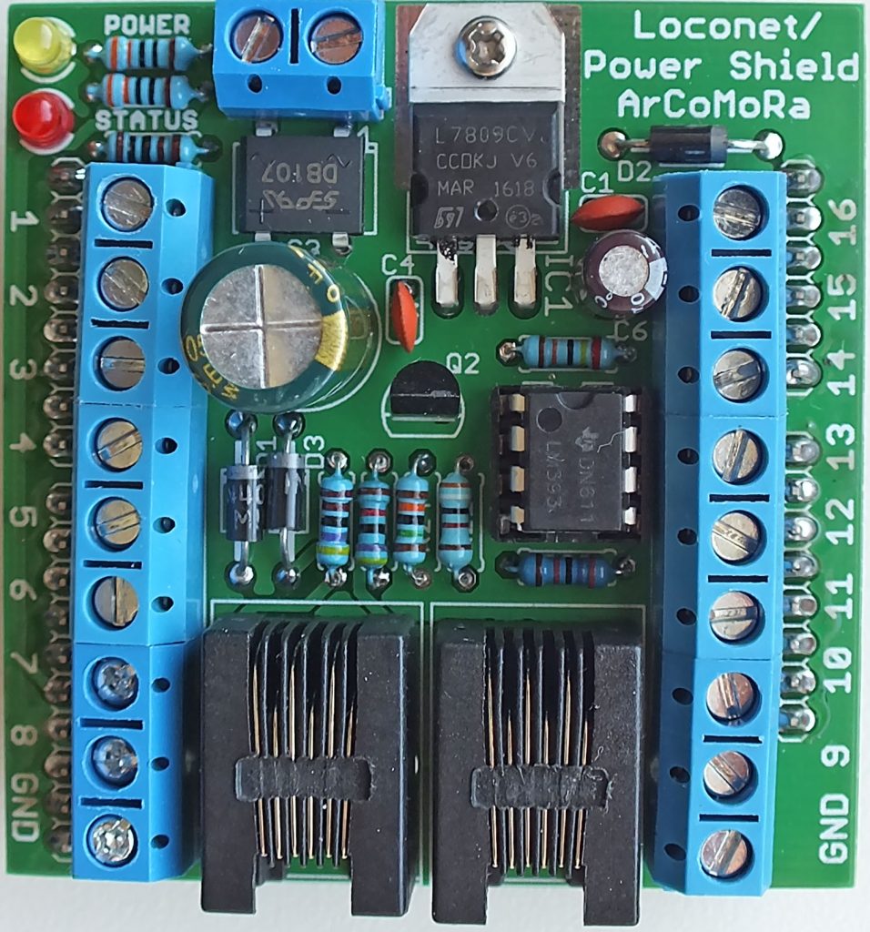
This shield can be placed on an Arduino UNO or Mega. It makes from the Arduino a 16(UNO) or 58(MEGA2560) channel feed back encoder with LocoNet®.
The shield includes 16 inputs for sensors, a power supply for the Arduino and two RJ12 connectors for LocoNet. On a MEGA the normal MEGA pins must be used for sensors 17-58.
The Arduino can be uploaded with the free ArLoco program.
SOLD OUT! No longer available
The ArLoco program has the following features:
- 16 Channel, low or high active, feedback input
- Use of a maximum of 4096 addresses. So for each ArLoco you have to specify the required address range (1-16, 17-32,…, 241-256).
- Each input can have its own address.
- Optimised for both pulse detection (like reedswitch) and continuous detection (like current detection).
- Each port can also be set as output for controlling accessories via LocoNet
- Simple configuration with your PC. So no complex CV-programming!
- Powered by LocoNet or external power (12-16 V AC/DC)
- Supports LocoNet-T and LocoNet-B
- Each channel can be configured for pulse or continuous detection. (Channel 1 only for pulse)
- Continuous detection:
- Prevention of fake detection caused by spikes
- Prevention of fake detection caused by short current outage
- Ideal in combination with current detection print OKKIE or OkkieNext4x4
- Pulse detection:
- Generates a fixed length pulse of 1 second.
- Eliminates contact bouncing
- Prevention of a double pulse when driving slowly
- Ideal for use with reedswitches.
Price €6,95
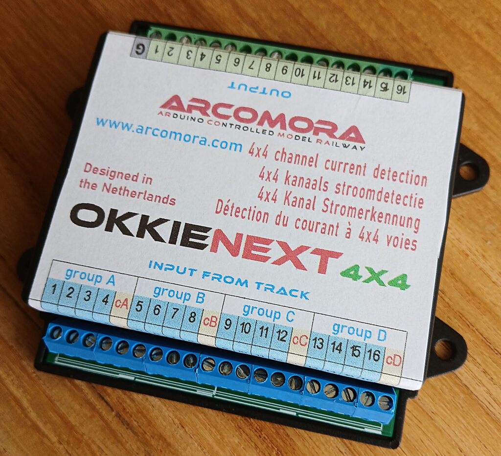
LocoNext
The LocoNext is a new SMD module that includes an ATMEGA328 processor.
So you don’t need an Arduino anymore.
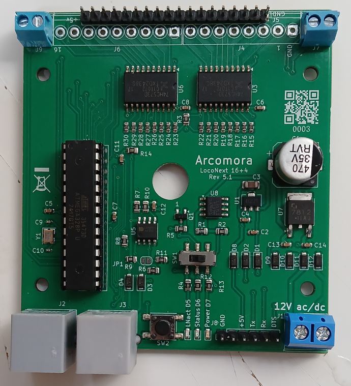
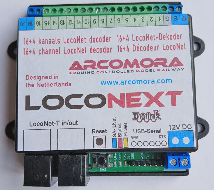
The LocoNext is designed to fit in a standard Arcomora enclosure.
It has the following features:
- 16 Channels LocoNet encoder/decoder
- 4 Additional channels that can be configured as input or output
- 4096 Addresses possible
- Address per channel adjustable.
- Can be used as standalone LocoNet device. No LocoNet enabled command station required.
Requires additional LocoNet-USB interface for direct LocoNet communication to PC. - Extensive debugging facilities.
- Easy to configure with your PC.
- Option to configure one port for an emergency button. Stops all trains immediately
- Powered by external power supply (12-16V AC/DC) , LocoNet or USB.
- Configurable on PC using Putty (terminal emulator program)
- Connections:
16 x 3.5″ screw terminals for inputs
4 x 3.5″ screw terminals for inputs or outputs (configurable)
1 x 3.5″ screw terminals for ground (ground)
2 x RJ12 connector for LocoNet-T
1 x USB interface (CH340) for connection to PC.
1 x 5″ screw terminal for 12V DC power supply - Current detection:
Provision against false alarms due to fault spikes
Provision against short power interruptions - Suitable for current detection with the Okkie/OkkieNext current detection boards ◦
- Can be directly connected to OkkieNext with a coupling board.
- Delivered with pre-installed LocoNext sketch.
- SMD technology, so easy soldering of a few remaining components like terminals and IC socket
Price: €15,95
OKKIE8 (SMD kit)
- Current detection print for 8 track sections
- 8 Screw terminals for input from tracksections
- 8 Screw terminals for output to ArLoco shield
- Option: Dupont pins for output
- GND screw terminal
- Screw terminal for Common track
Price: €6,95
SOLD OUT! No longer available
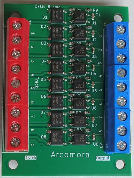
OkkieNext4x4 (SMD kit)
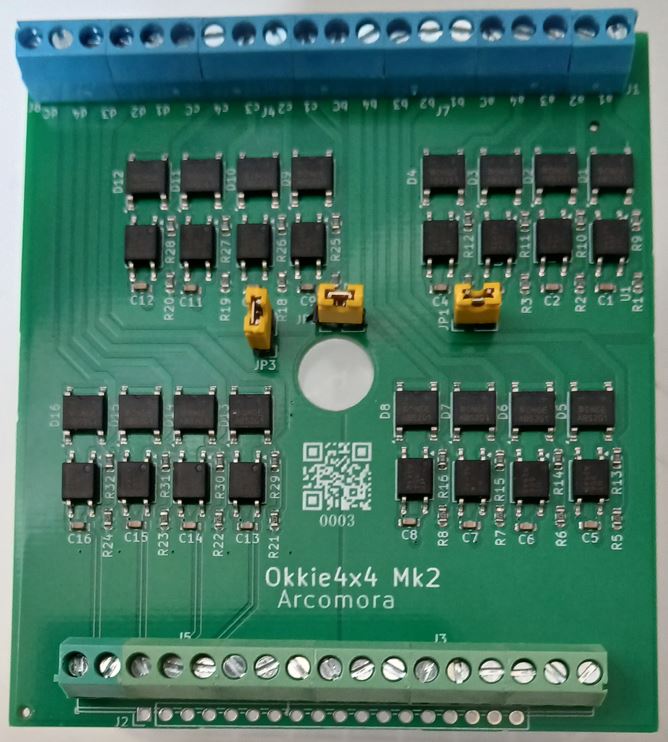
The OkkieNext4x4 is a current detection SMD module with 16 inputs for 16 track sections and 16 outputs for connection with a detection encoder like the Arcomora LocoNext module.
The inputs and outputs are electrically separated by optocouplers.
The OkkieNext4x4 has 4 groups with each 4 inputs and a common input.
In that way you have 4 independent groups for current detection.
By placing jumpers the groups can be combined to form groups of 4, 8, 12 or 16 inputs.
Features:
- Current detection print for 4 x 4 track sections
- 16 Screw terminals for input from track sections
- 16 Screw terminals for output to LocoNext
OR 18 Dupont pins for use with coupling pcb - GND screw terminal
- 4 Screw terminals for Common track. Each for 4 sections
- By using jumper you can create groups of 4, 8, 12 or 16 inputs.
- Delivered as SMD-print; you only need to solder the the terminals.
- Designed for use in a box. Box can be ordered separately.
Price: €14,95
Couple print
The LocoNext and OkkieNext can be connected with an easy to use couple print.
There are 2 versions available:
Standard version: simple pcb for connecting both modules with included Dupont pins.
Led version: SMD print with leds, indicating a detected train. Led remains on when train is in section.
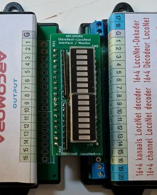
Print connects OkkieNext4x4 with LocoNext.
Note:
When ordering a couple pcb together with a LocoNext and OkkieNext4x4 these modules will be delivered without screw terminals.
The couple pcb is delivered with all required Dupont pins.
The extended ports of the LocoNext can only be used with screw terminals.
Price standard version: €2,75
Price Led version: 4,95
Combi package
You can also order a combi package.
It contains:
– LocoNext, pcb + components
– OkkieNext4x4, pcb + components
– Couple pcb with led indicators
– 2 standard boxes with stickers
Price: €42,95 (NO USB interface included)
This went together very easily thanks to following the clear instructions. I’m using it along-side some Digitrax BDL16 units. Make sure that the number you assign it doesn’t duplicate a number assigned to a BDL16 as it won’t be recognised. This may seem obvious, but wasn’t to me initially.
Just a question: does the okkie also work/report to a dcc++ arduino or to jmri?
Okkie is just a passive electronic circuit and thefore not related to any software product. The output voltage of an Okkie drops to zero if a current is detected on the input. It must be connected to a device(like an Arduino) that holds the Okkie output at 5 V by a pull up resistor.
The ArLoco shield and sketch ‘produces a LocoNet signal that can be picked by other LocoNet devices. Therefore there is no relation with DCC+ or JMRI.
Beste Nico,
Waar kan ik voor de Loco Powershield en de Okkie de bouwinstructie vinden? Ik kan soms via de plaatjes afleiden welke weerstanden erin moeten. Echter is het voor mij soms lastig aflezen. Ik heb liever de werlekijke weerstandswaarden. Dan kan ik ze effe nameten zodat ik niet de verkeerde exemplaren monteer.
Hallo André
Wat dacht je van de ArLoco/Okkie handleiding op de downloadpagina
Hi,
I’m new to Arduino, I was trying to load your code using the Arduino IDE but was getting an error. Then after doing some google searching, I was told to use version 1.06 and that worked.
avrdude.exe: stk500_getsync(): not in sync: resp=0x00
I see, Mostly it is caused by a corrupt bootloader. On my download page there is a document on how to fix this.
Hi John,
Why did you use thr IDE? You don’t need it. ArLoco is automatically uploaded when you start ArLoco the first time.
What went wrong?
Nico
Hi,
Do you have a version of this board that has 16 outputs instead of inputs ?
Hi John,
What do you want with 16 outputs? It is a feedback encoder and all such encoders have only inputs. Please explain.
Nico
Hi Nico,
I built this control panel using Team Digital hardware which gets expensive. I wonder it I can build one for cheaper. https://www.youtube.com/watch?v=M1tKq7kpXB8&t=7s
Something like this http://teamdigital1.com/prod_catalogue/src162e_product/src162e.html
has 16 inputs for pushbuttons and 16 outputs for led’s.
Thanks.
For that purpose I have the ASAR sketch (Analogue Servo control with ARduino)
You can control upto 12 servo’s without led indication or 8 servo’s with led indication with 12 momentary switches.
https://forum.beneluxspoor.net/index.php?topic=69109.0.
ASAR is no part of Arcomora, so documentation only in Dutch available. Sketch is in English
Hi,
First of all, thanks for a nice piece of work!!
I have one problem those. The software does not recognize the MEGA2560, it thinks it is the UNO. The introduction message is:
“ARLOCO, the ARduino LocoNet feedback encoder
UNO version 2.2”
and it has 1 to 16 sensor inputs.
I am missing anything?
Hello,
How is the OKKIE powered, and what is it’s (idle / max) power consumption (or current draw)?
Won’t the diode bridge design cause a voltage drop of about 1,5v of the track power, causing trains on a track section monitored by OKKIE to run a little slower than on a track section without OKKIE?
Hi Nico,
The ArCoMoRa generates a DCC signal to Loconet depending on its inputs. I guess the DCC signal would be replicated in the track signal. Would these DCC signals be able to used by the MarDec to activate accessories attached to the MarDec?
Thanks, Ted
Hi Ted,
Arcomora generates nothing. It is just a name for a railway automation concept based on an Arduino.
Mardec and Arsidec are sketches that generates nothing but uses DCC to control accessories attached to the Arduino.
ArLoco is a sketch that accepts and generates LocoNet signals for occupancy information. The ArLoco shield can use the DCC signal on pins 1 and 6 of the LocoNet cable for powering the ArLoco shield but does not use the information in it.
Nico
Hi Nico,
Sorry, I got the wrong word. My query should have read:
“The ArLoco generates a DCC signal to Loconet depending on its inputs. I guess the DCC signal would be replicated in the track signal. Would these DCC signals be able to used by the MarDec to activate accessories attached to the MarDec?”
Cheers, Ted
Ì repeat:
ArLoco is a sketch that accepts and generates LocoNet signals for occupancy information. The ArLoco shield can use the DCC signal on pins 1 and 6 of the LocoNet cable for powering the ArLoco shield but does not use the information in it.
ArLoco does certainly does NOT generate DCC signals.
Nico
Yep, I think it’s becoming clearer. Thanks for your response.
Cheers, Ted
Hi Nico.,
New to dcc, (so excuse o about these basic questions):
I bough an a) ex-cbs1 command station ,
b) your double dcc next module (and usb module) to control servo based turnouts.,
and then c) I now also want to add block detection and automate with JMRI all this stuff (with a macintosh), throttles by wifi with iPads.m or iPhones.. New n scale layout from 0.
Q: for c) can I use your loconext /oki4x4 modules with modules a) and b) described above, or do I need another piece of hardware?
How should I connect /wire all of this to work toghether?
Thank you very much,.
With DCC++EX you can connect an Okkie or OkkieNext directly to the command station. In case you have many sections use an additional IO expander.
You don’t need an ArLoco or LocoNext.
Ask Google or ChatGPT for more info.
Believe me Nico, i’ve spent countless hours browsing internet for this, and can’t find it. Great news I need nothing but okkie4x4 for occupancy detection., that makes this the cheapest and easier implementation of block detection for dcc++, by a long run.
I’ll order some okkies, but please include in the package a brief explanation on how to wire them for dcc++.
Nico, all clear with ChatGPT as for you suggestion,. It gave me a complete and very clear explanation.
Have you thought about a sketch for MQTT pub/sub for okkie and DCCnext (the very ChatGPT suggested this communication procedure when desling with several modules, btw)? That would be really nice,.
Thanks a lot for your answers and your nice work.
Hello Nico,
What is the threshold for current detection with the Okkie?
I’m interested in getting some to use but would like to know if its sensitive enough to detect resistive wheels as well as locos?
Thanks,
Joel
Hi Joel,
Just a few mA. is enough. We test Okkie with a 10k resistor as replacement for a loco.
So your resistive wheels will probably not be a problem
Hello Nico,
Is there any plan to increase the number of supported loconet addresses for ArLoco? I’m guessing the limitation is perhaps outside of your control but i don’t think 256 addresses wont be enough for my project.
Thanks,
Joel.
“i don’t think 256 addresses wont be enough for my project.”…
i meant to say:
i don’t think 256 addresses WILL be enough for my project.
Hi Joel,
Currently I have no intention to increase the number of addresses.
That must be a very large project.
May be some time in the future.
Nico
Hi The current setup for the Arloco works for Loconet Is there any way that the Arloco would work with say a lenz system that uses xpressnet?
Hi Daniel,
No. The ArLoco is only for LocoNet. XpressNet is a completely different protocol.
Nico
Can this be loaded to Arduino mini Pro ?
You can load it on a Pro Mini, but you can’t use the ArLoco shield.
Thanks for prompt response. I tried and program says failed to load the sketch.
Please help how to load it to Pro Mini.
Use the Arduino IDE to upload ArLoco.ino. Set the board type to ProMini and set the correct port number.
ArLoco.ino can be found in MyDocuments/Arcomora after installing the software (Windows only)
But I do not support it!
Hello Nico,
I am building a small layout and running it with DCC++ on Arduino with motorshield and JMRI on Raspberry Pi as the controller.
The DCC++ Basestation is connected to the JMRI using USB.
I was looking into the possibilities of JMRI and satellite systems and wondering if the ARLOCO shield can also be used to act as an interface between Loconet and JMRI ? Same as the (usually expensive) Loconet Hub or Buffer used to interface with a PC which acts as a command station using Rocrail or Koploper or JMRI.
Hi Martin,
The ArLoco can not act as a LocoNet-master.
So you need another device that can act as LocoNet-master.
Nico
Hi Nico,
I have a Digikeijs DR5000 and use S88N for occupancy detection through DR4088. I have an Arduino that controls Tomytec moving N-scale buses. I like to interface the Arduino to the DR5000 to get some feedback from the buses visible on my iTrain- screen.
Three simple questions about the ArLoco:
1) Can I use the DR5000 Loconet port to interface to an ArLoco- Arduino?
2) I studied the manual. The ArLoco wiring diagrams are confusing to me as the ArLoco print seems completely stand-alone. How is are external contacts wired to the Arduino and subsequently to the ArLoco (or the other way round)?
3) in my case the Arduino UNO also has to execute my own code and control stop solenoids for the buses. Is there ample Uno CPU time left over to execute my code?
1) Yes
2) The ArLoco print is a real Arduino shield. So it must be placed on top of an Arduino UNO or MEGA.
3) Yes. But do you want to add your own code to the ArLoco sketch or write another sketch?
Nico
Hi,
I just need a hardware interface between the Arduino and the Loconet to send signals from the Arduino to the Digitrax Controller via the Loconet jack. Would this work for that ? I know I can build one, but I was looking for a lazy shortcut, that’s all.
Thanks
Vibhas
Hi Vibhas,
What LocoNet signals do you want to send?
The ArLoco shield is primarily intended for use with the ArLoco program.
The ArLoco program is designed for train detection; it reacts on a level change at the sensor input.
But you can always create your own sketch to fulfill your personal needs.
Nico
Loco control signals – start, stop, direction, light control, whistle control etc. Not for accessories or decoders.
Basically I want to use the Arduino to control train movement. I can use a motor shield, but I am afraid that it wont take enough current for more than a couple of locos. So I am thinking that I will use the Arduino to programmatically send Loconet signals to the Command Station (just as a the hand-held throttle would) and utilize the Command Station and Booster’s capability to handle higher current. For that I would need to interface the Arduino to the Command Station / Loconet and hence I am looking for an adapter.
Hi Vibhas,
For such application the ArLoco shield is NOT what you need.
Nico
The manual state that input 1 is impulse only, does it mean that one ARLOCO Shield on UNO and 2 OKKIE gives me only 15 inputs and not 16?
Hi Nicolas. That is correct.
Nico
hello
how to reload the new version of ARLoco version 3.1 on an old one already installed ?
With arloco putty ? In this case, the uno normally starts and is not not in load state.
With IDE
Thank you
Hi Alain,
Use the upload tool. The shortcut is on your desktop.
Nico
Hi
Would it be possible to have Arloco to report back Railcom information?
I looking for trainid and direction.
/Stefan
Hi Stefan,
No that is not possible. You must turn off Railcom when using ArLoco.
Nico
Hello Nico
I have been using your Arloco and Mardec with great success, I have Railcom detectors (Digikeijs) on the layout and the Arloco/Okie detectors. You have stated above to “turn off “ Railcom when using Arloco ? Please explain why.
Thank you Martin
Hi Martin.
If you have no problems with Railcom detectors then don’t worry.
It works for you.
The problem is merely related to the z21 or Z21.
I don’t know in detail what the problem is
Another user had problems with Railcom turned on and his z/Z21.
When turning of the problem was solved.
Nico
Hello Nico
I forgot to update this thread, I replaced the Z21 with a Digikeijs Dr5000 and it all works. Many thanks for your great products.
Just a thought is it possible to make a Loconet turnout controller like your Mardec? I have 13 old Arduino’s Nanos running your Mardec software but I get the feeling things would be better on the LocoNet bus not the DCC ?
Hi Nico
I would like to read the status of points (turnouts) from a 2-way switch underneath. Is there anything to stop me doing that with this board? I guess I’m asking: is there anything in loconet which is different for a ‘general purpose closing contact’ like checking the status of a point, versus checking for track occupancy by a train?
Thanks
Hi Ed,
I think there is no fundamental difference between checking a closed reedswitch in a track or any other closed circuit.
I don’t know how your 2-way switches works but you can try ArLoco for testing the status of the turnout.
Nico
Might it be possible to reconfigure the arLoco to work with an NCE CabBus system?
No, that is not possible. ArLoco uses only the LocoNet protocol
Hi Nico
Sometimes the board after power up comes up in “Edit” mode instead of “Normal”
mode. Even if we restart the board with “Reset” button it comed up in “Edit” mode.
To fix it we need to connect a computer and manually set it in “normal” mode.
Have seen this before?
Stefan
Hi Stefan,
I have heard that problem with Arsigdec, not with ArLoco.
I have no explanation for it.
You say ‘sometimes’. Therefore I guess that a single bit in EEPROM is toggled.
Nico
Hi Nico
We have a teory. I could maybe be the power supply. We have 5 V from a central supply and then distributed to all the card on the same modul (240 x 120 cm).
I have changed it now and we are now using the 5 volt regulator on the Nano board. So the board gets 12 V frpm tyhe central power supply. It will then have 5 volt and not something between 4-5 volt depending how long the wires are.
Stefan
Hi Stefan,
Is the problem solved with this change?
Nico
Hello,
I ‘m constructing a small DCC layout but I also have many analogic locomotive. I was wondering if I could use the DC (detaching the DCC central, never DC and DCC together).
So my question: if I connect the DC to the tracks will I damage the Okkie or the Arloco?
Thank You.
Fulvio
I guess it will not damage an Okkie and ArLoco. Current detection remains possible. But test it first before applying it to your track.
But don’t connect DC to an DCCNext. It is useless.
Nico
Kan ik de ArLoco gewoon opnemen in mijn bestaande loconet netwerk?
Als ik hem wil gebruiken als terugmelder (massadetectie) heb ik dan ook een Okkie nodig?
Een ArLoco kan gewoon in je LocoNet netwerk worden opgenomen. Hou wel rekening met de adressering. Voor ArLoco heb je alleen de adressen 1 t/m 256.
Een Okkie is alleen voor stroomdetectie, niet voor massadetectie.
Lever je deze ook geheel gebouwd?
Nee, deze wordt niet gebouwd geleverd
Nico,
Ik heb de bestelde Arloco’s inmiddels gebouwd en geïnstalleerd, so far so good.
Als ik de bezetmelder activeer op mijn baan gaat de desbetreffende melder ook netjes branden. Echter na een aantal seconden gaat hij staan knipperen.
Ik gebruik massadetectie en hierop staat de Arloco dan ook ingesteld.
Waar moet ik dit zoeken?
Nico,
Please correct my thinking if I am wrong- all segmented track is powered via Arloco?
Hi Maciej
The tracks are always powered by the DCC/Motorola signal generated by the command station.
An Okkie only detects the presence of a train in a specific section. The ArLoco forwards that to the command station/PC via LocoNet
Nico,
An OKKIE of course?
Hi Nico
I built a Mega version to use on a push button matrix panel. However when I plug the LNet connector in the unit starts to show random triggering of the inputs? If I just connect the USB and look at the laptop out put everything is fine, a button push gives a message. I have tried using the DR5000 ( shows only a few random inputs) and an ESU LNet adaptor ( goes a bit crazy with 50% of the inputs triggering) any thoughts?
Do I absolutely need iTrain or TrainController, or may I:
a) run ArLoco with just a DR5000 as the Command Station using the DR5000’s on-screen commands;
b) run the system with JMRI (with a layout panel) connecting through the DR5000 via loconet to the ArLoco board?
Thanks, Don
Hi Don,
With ArLoco you always need a train control program.
Option A: The DR5000 can show the occupied section but can’t react on it.
Option B: That will do. JMRI is a train control program and can react on an occupied section.
Nico
Hi, I am looking to get some Okkies and I am interested about what is different in the new version. Is it just the number of channels? Do both have the same voltage drop (due to the bridge diodes)? Can both of them be used at the same time?
Thanks for the clarifications!
The OkkieNext is the same as 2 single Okkies on a single pcb. They are used in exactly in the same way as an Okkie. So you can use them together
Hi Nico,
My project is a N scale layout DCC powered by an ECOS.
I’m interested in your detection system, wonderful job from you …
Some part of the layout will be switched between DCC and conventional DC for analog locomotives to run. I’ve read above that your OKKIE should work also with DC, I will try.
Some questions:
1/ It’s sayed that a train controller software is necessary. Given that my ECOS will be able to indicate the occupied sectors through a L.net converter (Loconet to ESU ECOS), is it correct I don’t need a train controller software with ArLoCo and OKKIE ?
2/ Will the L.net converter fromESU able to translate the occupancy messages from ArLoCo?
2/ Wy did you put a 4k7 resistor on your OKKIE schematic ? I saw numerous times the same schematic without that one. Is any specific role ?
Thank’s for your support
Yves
1/ Can you program an ECOS to react on an occupy detection? I don’t think so. The ECOS will forward the occupation to the computer. The computer can react by e.g. stopping a train to prevent collision.
2/ YES
3/ The most Schemas I found on Internet do have the 4k7 resistor.
Many thanks for the prompt delivery of my OkkieNext devices, as always, the build was simple and straight forward.
My plan is to move away from Loconet and use DCC-EX (controlled by itrain). My idea was to use the Okkienext devices for block detection but cannot find a wiring diagram for this setup (ie not using an ARLoco device). Is this use a possibility? or am I barking up the wrong tree? (might have been worth me asking this question before buying the devices but that’s my bad not yours!)
It’s amazing what goes through your mind in the dead of night! having reviewed all documentation I could find I have worked out the wiring. I know you have probably said this many times, but it dawned on me the Okkienext is just a passive device that monitors current. Therefore connect one output from the DCC++ Arduino to the “common track”, connect the other output to the “common” on the Okkienext and then connect the other track to the sensor port.
So simple once you “get it”.
I then configured DCC-EX to read the sensor as a Pullup and pow! works a treat! my problem with the Digitrax Loconet route was that there was such a lag on reading block sensors it was causing issues with automation. The responsiveness when using the Okkienext is lightning fast.
It also means that I can position multiple Okkienext devices around the layout and thus simplify the wiring. Onwards to the next unforeseen issue (I am sure it will be just around the corner!)
Have a great Christmas Nico and thanks for another excellent product.
And here is the unexpected problem. I have connected my second OkkieNext onto the layout. it worked for the first 10 minutes and then today, when I turn everything on the device is ‘dead’.
To make sure it wasn’t wiring, I disconnected everything from the device except the power feed and the ground. When testing the circuit between the common and the “negative” track I see as 10.7 V a/c/ (as expected). However when I check between ground and one of the sensor outputs I see no voltage (as the track is disconnected everything should be registering unoccupied). on the working unit I see a voltage if the block is unoccupied (4.78v) and almost no voltage for an unoccupied block (0.07v).
Do I conclude the new unit has suffered a failure? always find new devices (from all manufacturers) either fail fast or work forever! If so, are there any other tests I can perform or do I just need a new device?
Hi Nico,
Once again, thanks for your quick response to my query. The great news is that the OkkieNext is operating just fine and it was my interpretation of how to connect the second device that was wrong (and my perception it ever worked is questionable!).
To give some context, the idea was to extend my current configuration (where an OkkieNext is delivering high speed block detection when connected directly to an Arduino Mega running Dcc-EX) to an area of the layout some 2.5 metres from the first OkkieNext. This would avoid having long wires running all over the place and keep things neat and easy to manage.
My idea was to use an I2C hub from DFRobot to do this. ie connect the OkkieNext sensor outputs to the I2C hub and just have an I2C bus running back to the DCC-EX Arduino. What I hadn’t appreciated was the importance of the onboard pull-up sensors the Arduino provides (despite your clear instructions). There may have been a way around this but it was beyond my limited skills.
I have now installed a second Arduino mega connected to the second OkkieNext, on the other side of the layout running EX-IOExpander and then connected the two Arduino’s using the I2C bus. This works perfectly.
The combination of DCC-EX and your Okkienext devices perform significantly better than my old Digitrax solution at a fraction of the cost. I will be back for more soon!
I’m glad I saw this post! I am getting ready to do the same thing, although my DCC-EX command station is the CSB-1 which is based on the ESP32. As such, two hurdles – one, it is 3.3v vs 5v, and two, lack of available on board GPIO (love all those pins on the mega 2560!). I can level shift as needed, and I will probably have two mega 2560s as IOExpanders. My OkkieNext units will be connected to the IOExpanders – getting away from Loconet in favor of direct connect to the command station. Cheers!
I just amended my plan – I will use the MCP23017 (or possibly TCA9555) I2C GPIO expanders with my DCC-EX. The connections from the OkkieNext to the MCP23017 will need pullup resistors. I also won’t need level shifting as the MCP and the CSB-1 are both 3.3v. Just tested on the breadboard! Cheers!
Normally DCC-EX is used with an Arduino and JMRI or RocRail as train control program. An Okkie is then directly connected to an Arduino port.
Example: https://www.youtube.com/watch?v=53Im_XciouU
Bonjour, peut on mélanger Arloco avec d’autres systèmes de rétrosignalisation ? (ex: Digikeijs DR 4088 LN-CS)
Merci
Yes you can mix with other LocoNext encoders
Nico, for the Arloco shield external power supply, is it ok to provide voltage above 12vDC? I the manual page 10 diagram shows 7-12vDC. Page 12, testing 12-18v AC/DC. I like to provide 12.5vDC as external power for regular operations?
Thank you
Bonjour, je souhaite pouvoir utiliser 58 capteurs de rétrosignalisation. Il faut combien okkiesnext reliées à une carte Mega2560 ? Merci.
For 58 current detection sections you need 58/16= 4 OkkieNext
Nico
and i need 4 arloco too ?
Yes. Or one Arduino ATMEGA2560 with one ArLoco shield
Hi Nico,
What’s the model number of the original RJ11 connector (like the one in the picture above)? I need to purchase few as they better suit my installation.
Thank you
It is a RJ12 (6p6c) connector.
I do have them in stock. Use the order form if you want some.
Nico
How to debug LOCONET?
I have hooked up my ArLoco to my DR5000 and while II can see the detection messages in the putty output. Nothing shows up on the digikeijs unit over Loconet. I have tested before with DR4088LN-CS to verify the loconet bus works on the DR5000.
I have the ArLoco shield on a Medga256 so I have a large numer of ports. And I did setup the unit to start counting ports from 201 onwards but nothing shows up on the DR5000.
Is there a way to determine if the loconet bus is setup correctly on the ArLoco shield?
Any other suggestions to troubleshoot this?
Hallo Hugo , wil graag in kontakt met je komen over de setup van LocoNext op de DR5000.
Mail: abadegroot@hotmail.com
Op de DR5000 kies je als digitaal systeem ‘LocoNet’. In ‘Connection’ tab van de Block editor kies je ‘2: LocoNet Plain Number
What abut the LocoNext? I see it on the order form but could not find no reference to it on the website.
Ni Nico,
Having been successful with OkkieNext devices I have now installed an OkkieNext4x4. Whilst power is flowing through the device as expected, I cannot make the block detection work as per the old devices.
Can I test the OkkieNext4x4 with a multimeter ? and if so, how? ie what would I expect from specific pins etc?
Hello,
Your manual states that “you cannot connect an output from an OKKIE detector or any other presence detector to input 1 of the ArLoco.”
Yet it works?
What’s the contraindication?
Sincerely,
Hi Christian,
How did you test it? ArLoco loaded on the Arduino?
Port 1 is connected to pin 0 of the chip. That is the Rx pin. It conflicts with other IO
Hi Nico
It worked, but now I have faulty optocouplers. That might be the cause.
Hi Nico
Will you publish the sourcecode for Loconext?
Good that you now have full adressrange. Will you update Arloco to have the same range?
The source code is part of the latest release.
The ArLoco sketch will also be upgraded to 4096 addresses and an option to set a port as output. Will be released soon.
Nico
Hallo Nico,
erst einmal : Tolles Projekt, was du da aufgesetzt hast – Glückwunsch.
Habe eine Frage zum Anschluss des OkkieNext 4×4.
In der Anschlussskizze und im Text habe ich keinen genauen Hinweis darauf gefunden, ob die Stromerkennung ausschließlich über die Masseleitung erfolgen kann oder ob auch die Plus-Leitung zur Erkennung genutzt werden kann.
Lieb Grüße
Uli
Ich verstehe Ihre Frage nicht ganz. DCC hat keinen GND- und Plus-Anschluss.
Beide Signale sind gleichwertig und reichen von +15V bis -15V (je nach Zentrale).
Im Anschlussbeispiel können Sie die gelbe und orange Leitung wechseln.
Wir nennen auch die gelbe Leitung Common Track und die orange Leitung Common DCC
https://www.arcomora.com/wp-content/uploads/2024/09/OkkieNext4x4DEmk2.pdf
Hi Nico!
I have a LocoNext / OkkieNext connected using the PCB connector. Is it possible have the LocoNext report status of a toggle switch connected to the OkkieNext?
I tried using a 10k resistor with a toggle switch to simulate a motor load, but that did not trigger the OkkieNext. Thanks!
Can the OkkieNext4x4 operate at 3.3 V ?
I am considering interfacing it with an Arduino variant that only runs at 3V3.
regards Mark
Yes you can use it. But you need an pull-up resistor in the Arduino: pinMode(pin, INPUT_PULLUP);
Nico
Hi Nico
First of all that for you good products, and the good documentation 🙂
2 questions:
1) I am experience some noise, where the with Arloco, where it is flickering Opcupied/Free, can i just for that in the software
2) Why is the input on Mega pin 48 and not e.g. 2?
1) Mostly caused by insufficient wiring. Try to vary with the ‘Delay before occupied’ time.
2) That is hard coded in the LocoNet library.
Thanks a lot !!!
HI Guys,
Really interested in this ArLoco/Power shield (DIY kit).
Do you have to solder everything on the board yourself?
Also, would it work out of the box with the Z21 black? just plug the cable from it run?
Please let me know.
Kind Regards,
ADrian
Hi Adrian,
The ArLoco shield is the last print that does not contain SMD components. So you have to solder it all yourself.
Because the Z21 has LocoNet ‘on board’ you can directly connect it to the LocoNet-T bus.
If you don’t want to solder everything I advice the LocoNext. It is a SMD print with very little soldering yourself.
The ArLoco shield and LocoNext are mostly used together with an Okki8 or OkkieNext for current detection.
Nico
HI Nico,
Thank you very much for responding and clearing that out.
Yes, lookingh for something that can work directly plugged in to the Z21 without too much hastle.
I can solder some components. I assume it comes with them and instructions?
Looking to use this for Itrain, so would i need the others or i can just get the Loco Next?
Kind Regards,
Adrian
I prefer the LocoNext over the ArLoco shield:
– more functionality
– easy to build
– no Arduino required.
Benefits of ArLoco shield:
– All ports can be set as output
– Can be used also on an Arduino MEGA.
See both manuals, then you can compare better.
Hello Nico,
As I am using a DCC_EX command station and using 2 OkkieNext all my input pins on the DCC_EX are in use. I am thinking to extend the number of inputs by using the LocoNet protocol.
Will a LocoNext do or do I also need an ArLoco Power schield?
Regards,
Felix de Groen
The LocoNext is useless for you. You need an IO extender like the MCP23017 on the DCC_EX station.
Nico