
The next step in decoding DCC has arrived!
NEW: The PowerNext
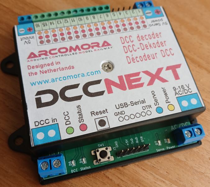
What is it:
A single pcb that combines an Arduino UNO and the existing Arcomora DCC/Power shield.
This SMD (Surface Mounted Device) print contains most components already soldered.
You only have to solder the remaining components. Easier and more reliable.
It contains:
- Internal power supply. Input: 9-16V AC or DC
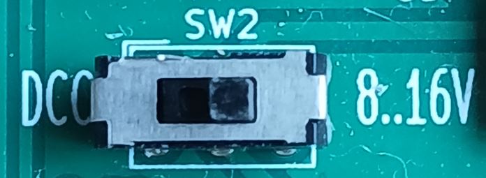
- Can also be powered by DCC. To be selected with jumper or switch.
- Can also be powered by external 5V.
- Input for DCC with led indicator and decoder circuit
- ATMEGA328P processor
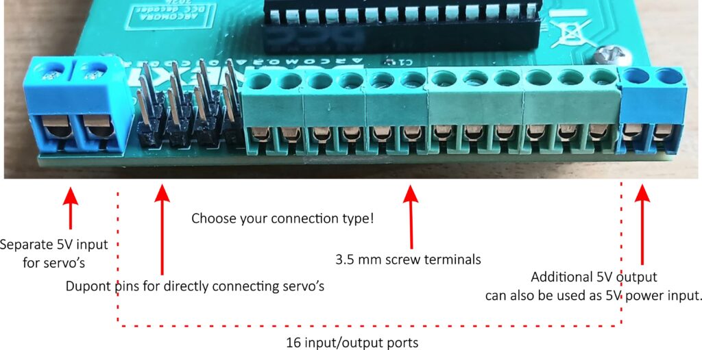
- 16 Outputs or inputs for controlling accessories and servo’s.
- Outputs with Dupont pins (for servo’s) or screw terminals
- Separate 5V input for servo’s connected to Dupont pins
- Additional 5V output for testing purposes (no servo’s) or leds
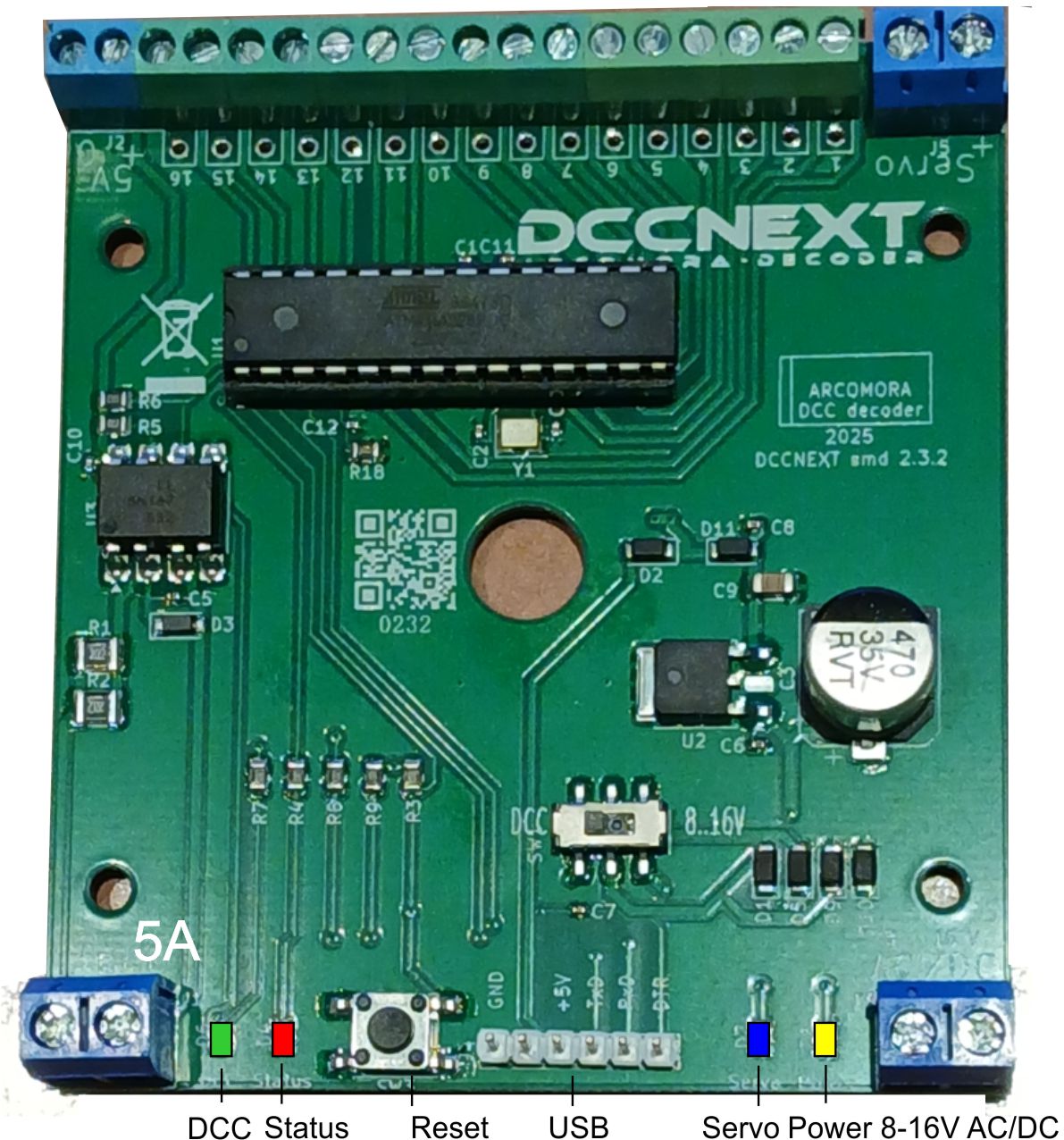
- Status led
- Power led
- Servo power led
- Reset switch
Interface
To keep the price low there is no USB interface on the board.
But an external USB interface(CH340) is also available.
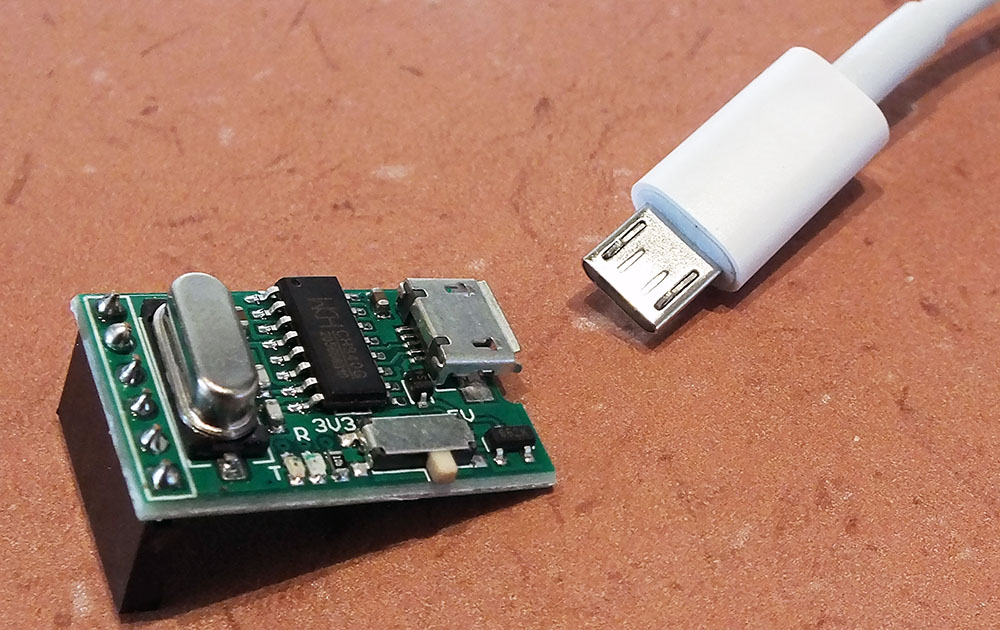
It can be used for multiple DCCNext decoders.
So you need only one! That saves money.
However it is advised to use an interface for each DCCNext and connect them to a powered USB-hub for a single connection to your PC.
Connections:
Usage:
- You can create your Arduino sketches for processing a DCC signal and upload them to the DCCNext.
- Upload the Mardec sketch for use as multipurpose DCC decoder for accessories and servo’s.
- Upload the ArSigDec sketch for use as signal decoder.
The board has four power options:
- Internal. Circuit powered by internal power
- DCC track signal or LocoNet-B Railsync
- External. Circuit powered by the 5V terminal
- USB from PC (Advised)
The power source can be set by two jumpers or a switch
Interested?
You can make a reservation for:
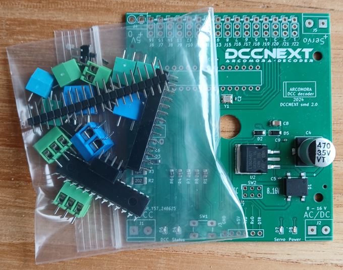
The SMD DCCNext decoder kit
Contains the SMD print and remaining components.
Price: €14,95
The USB-Serial interface including a cable.
Price: €3,25
Type: CH340
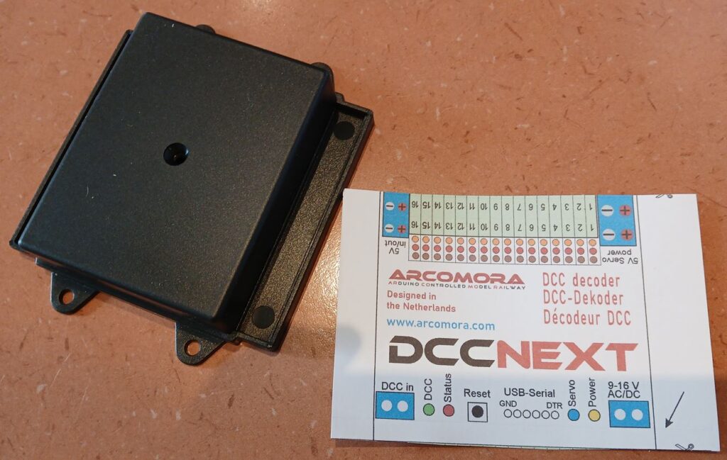
A box with text sticker. Price: €4,75
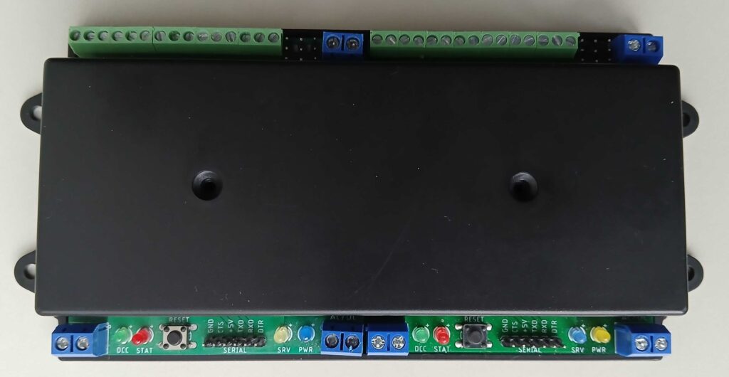
Double sized box. Can contain 2 standard pcb’s.
Price 6,95. Temporarily also €4,75
You can also order a completely assembled DCCNext.
An interface and/or box must be ordered separately!
The print is already soldered and tested. In the Remarks field of the order page you can specify how many ports requires Dupont pins for servo’s.
Just connect to your PC and upload Mardec or Arsigdec or your own sketch.
Price only €21,95
Click here to go to the order page
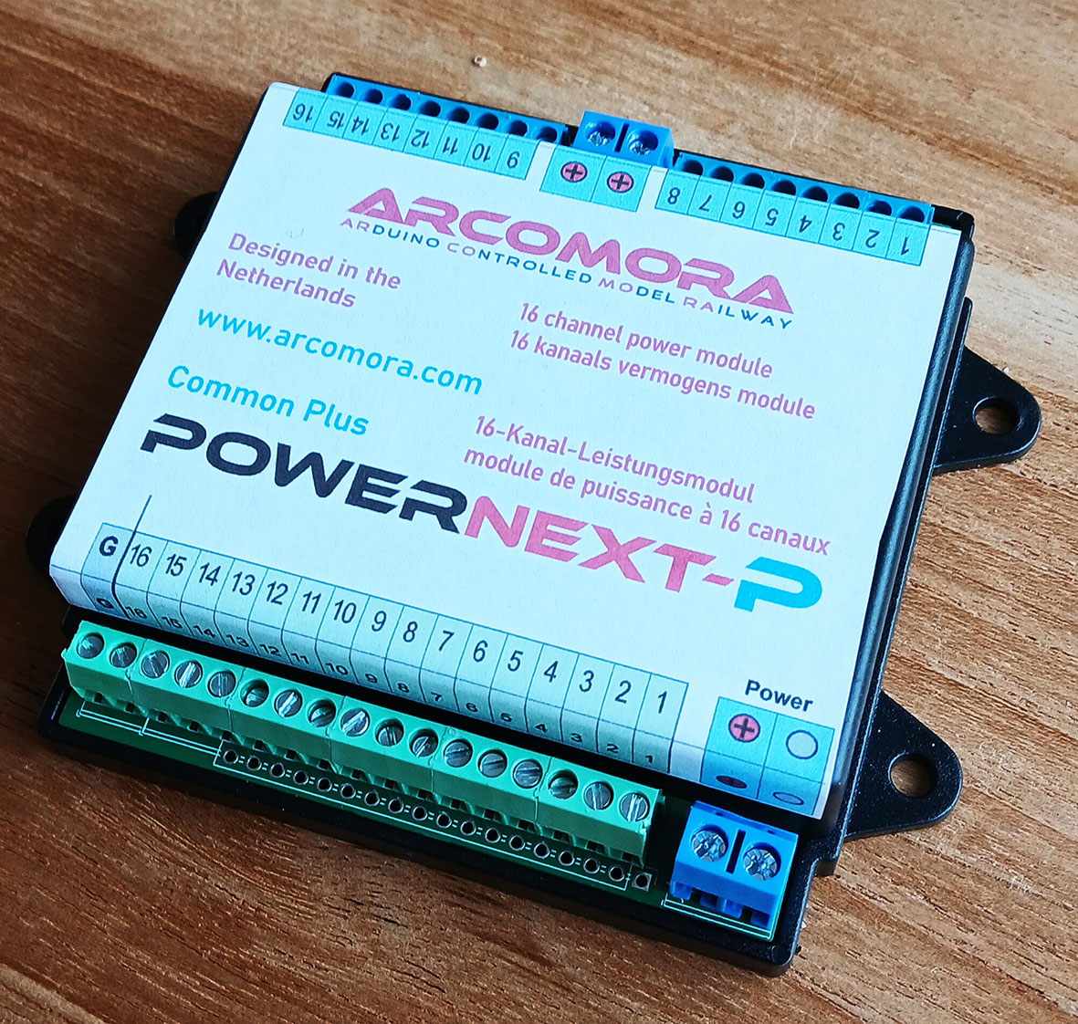
PowerNext
Sometimes you need more power then can be delivered by an Arduino or DCCNext.
In that case a PowerNext-P from Arcomora can help you.
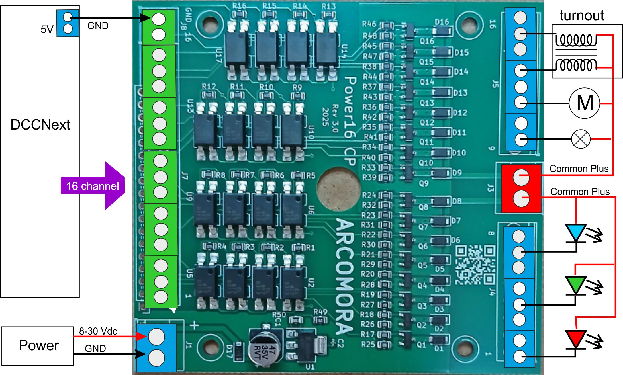
The PowerNext-P is a SMD board that can be used for controlling devices that require more current and a higher voltage. It can switch a maximum load of 2 Amp or a peak load of 4 Amp..
The main characteristic of the PowerNext-P is that all loads must use a common plus . It is designed for tracks where other electrical devices uses already a common plus. All connected devices must use the same voltage.
You can connect the output from a DCCNext/DCC-shield to an input of the PowerNext-P.
The input is fully separated from the output of the by an optocoupler; even the ground is not connected. This 100% galvanic isolation between input and output(blue terminals) prevents unwanted disruptions.
You can also connect outputs from multiple DCCNext/DCC shield to the PowerNext-P. Be sure to connect all GND from the DCCNext/DCC-shield to the GND input.
All outputs contain a suppressor diode. That makes it very suitable for turnout coils.
Typical application for the PowerNext-P with Mardec accessories:
- Turnout coils; require two outputs and a “Double one shot“
- On/off control for DC motor, lights or led strips and a “Single steady“.
- PWM control (slowly on-off-on) of DC motor, lights or led strips and a “Analog PWM“.
Price PowerNext-P only €13,95 (SMD kit)
For both modules an additional housing box with sticker (€4,75) can be ordered.
PowerNext-P
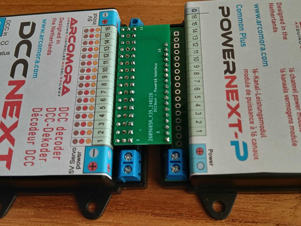
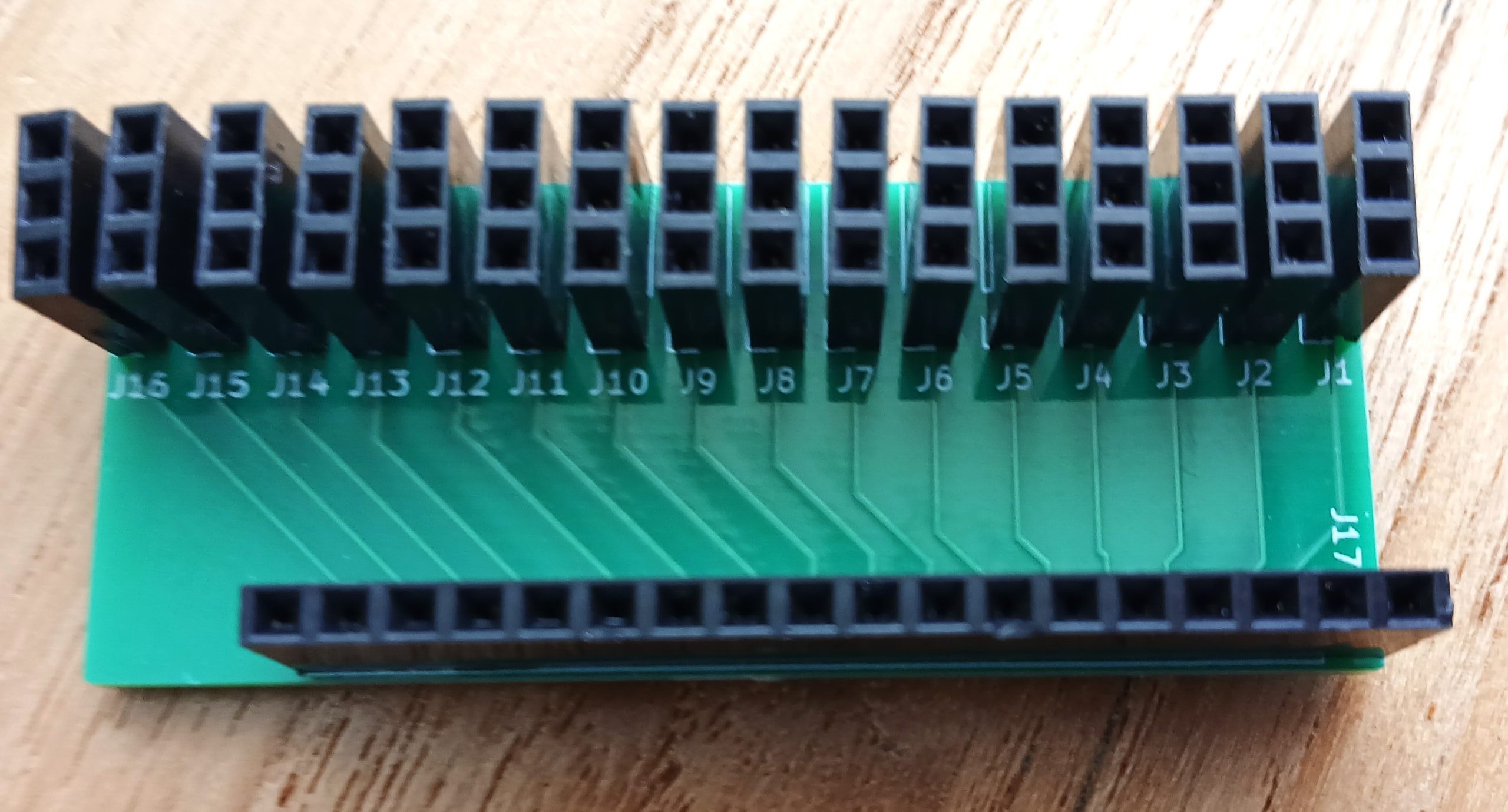
A couple print between the PowerNext-P and DCCNext is also available.
The DCCNext must contain 16 Dupont pins on all 16 ports.
Price: €4,50
Hello Nico,
In the dutch “Montage handleiding DCCNext” i see a LED between pin 3 and 4 of the 6N137. In all other schematics i know of there is a 1N4148 in that place. Is the LED indeed functioning the same as the 1N4148? Futhermore is the 220 pF capacitor placed between pin 2 and 3 of the 6N137. In the DDC circuit shown on page 7 of arsigdecmanualdb.pdf there is a 100 nF capacitor between pin 8 and GND. Can you explan the different choice to me?. Can I build the DCC circuit part as shown in the DDDNEXT diagram als a saperate single board as well?
Thnks in advance for responing.
Greetings, Chris de Groot
Hi Chris,
Yes the led functions the same as a 1N4148, so don’t worry.
Do you really think that I would sell it if it doesn’t work?
The 220pF capacitor also occurs on other schema’s of the DCC circuit.
Capacitor C4 of the DCCNext functions as the 100nF on the DCC/Powershield.
Nico
Hello Nico,
Thank you for your answer. Ofcourse I know it works, but I am not that experienced in electronics. I just wondered, and liked to know.
hello Nico
I have built 2 dcc next decoders.
one configured as a mardec, the other as arsigdec
They both work fine, without any problems at all
Thank you
Hi
Concerning the CH340 module. Do you use the DTR and the CTS signals on the board or are the just unconnected?
Hi Tomas,
As you can see in the schema of the assembly manual (download from download page!) the CTS is not used and the DTR is connected.
Nico
Hi Nico
Thank You for your help. I didn’t see, there were a schematics included in the assembly manual. But the pinout int the schematics doesn’t comply with the pinout on the assembly. RX/TX is placed different.
In the schematics, it is: GND, RX, TX, +5V, NC, DTR.
In the assembly drawing, it is: GND, CTS (NC), +5V, TX, RX, DTR
I suppose the assembly is the correct one?
BR
Tomas
Hi Tomas,
You are right.
I fixed the manual already a few weeks ago. But apperently I forgot to upload it.
Done now.
Thanks
Nico
Hi again Nico
If I download the: https://www.globalvisuals.nl/downloads/MountingManualDCCNext-UK.pdf – It still looks the same?
Where can I find the right CH340 module? I can find some similar on ebay, but not with micro-USB with the right connector.
Hi Tomas,
The file was replaced indeed. May be your browser picked it from the cache
Clear cache and try again.
You can order the CH340 interface by me or buy it at Aliexpress.
Search for: CH340 micro USB
Nico
Great – Much better now 🙂
I found the board at Ali’s at $1.20 🙂
BR
Tomas
Hello Nico, this is a very interesting development. My layout currently has over 70 servo operated turnouts using hard wired control panels feeding into servo interface boards. It works fine, except for a lot of wire. I’m currently expanding with another 20 turnouts and DCCNext has the potential to be useful. I use the NCE DCC system.
Just to clarify, I understand this board is essentially a multi channel accessory decoder. Using it to operate a turnout, please confirm I would need to generate a DCC accessory command from either the throttle, or a PC running JMRI or similar, or an encoder such as a Cobalt Alpha.
regards
Darryl
Hi Darryl,
Yes, the DCCNext requires indeed a real DCC command as specified in the NMRA specifications.
However accessories and servo’s can also be controlled by a switch connected to a port that is set as an input.
Nico
Hi Nico,
Am I right in thinking that a servo can only be operated one way by a switch connected to a port that is set as an input. I say this as on page 6 of the Mardec manual under Input Commands you say, “Nothing happens when the pin is made ‘high’ again”.
Thanks, Ted
Hi Ted,
That applies only to Mardec versions prior to version 5.
To rotate the servo back again the input must be made low a second time.
But Mardec 5 offers more options. Look in the manual:
An input can be activated in three ways.
1) By lowering the input. Nothing happens when the entrance becomes high again. (type D)
2) By making the entrance high. Nothing happens when the entrance becomes low again. (type U)
3) By making the input low or high. The accessory or servo “follows” the input signal as if it is controlled by DCC. (type L)
With this option, for example, a switch can also be converted by means of a switch.
With options 1 and 2, an input acts as a momentary switch.
With option 3, an input acts as a changeover switch. Just like a DCC command.
The activation method is requested when configuring a port as input.
Download the latest version of the manual!
Nico
Thanks Nico,
That’s wonderful. I’ll download the manual now.
Cheers, Ted
hallo
is het mogelijk om elke poort te configureren als in of output?
dus is het mogelijk om ze door elkaar te gebruiken.
mvg
Jan Hendriks
Hallo Jan,
Ja, je kunt met Mardec van iedere poort een input of output maken.
Mvg
Nico
Dag Nico,
Wat is de reden dat de DCC Next zijn instellingen kwijt raakt. Dat is mij deze week al twee keer overkomen. Ik heb de gegevens natuurlijk wel bij de hand maar het wel weer een aardig klusje om al de instellingen voor de servo’s opnieuw in te voeren.
Gr. Jan
Hallo Jan,
Geen idee waarom dat kan. Probleem niet eerder gehoord. Het lijkt erop dat het EEPROM niet helemaal goed (meer) is. Heb je dit vanaf het begin of is het pas na een tijdje fout gegaan? Heb je nog een andere DCCNext? Verwissel dan eens de processoren.
Is de voeding helemaal in orde? Geen spanningspieken of zo bij inschakelen?
Nico
Hallo Nico, goed idee om de processoren te verwisselen, ik heb nog een DCCNext liggen.
Voor zover ik weet zijn er geen spanningspieken.
De andere Mardec en de Arloco functioneren prima en houden de instellingen vast.
Wanneer jij nog niet eerder van dit probleem hebt gehoord zal het een toevalstreffer zijn.
bedankt voor je reactie,
mvg Jan
De DCCNext is een mooi stukje techniek dat mij, als starter in de digitale modelspoorwereld, alle functionaliteit geeft die ik maar kan wensen.
Als “herintreder” in deze mooie hobby wilde ik me concentreren op het bouwen van gedetailleerde landschapjes waar aanvullend de treintjes volledig automatisch doorheen tuffen. Door dit product te gebruiken hoef ik me niet meer te verdiepen in, voor mij, nieuwe programmeertalen en alles wat daar omheen hangt.
Je moet uiteraard wel kunnen solderen. Een soldeer-station met instelbare temperatuur en een dunne soldeertip is geen overbodige luxe. Maar aan de levering van het product zal het niet liggen. Alles is keurig verzorgd en zeer gedetailleerd beschreven in begrijpelijk Nederlands.
Een paar uurtjes solderen, software laden en de servo’s aansluiten en alles functioneert in één keer. Zelfs de goedkope servo’s van 0,90 euro per stuk via AliExpress voldoen prima voor de wissels die ik ga gebruiken.
Ik kan dit product dan ook iedereen aanbevelen. Voor weinig geld heb je een perfecte dcc-wisseldecoder.
Hallo Rob,
Bedankt voor je mooie woorden
Nico
Hallo Rob,
Je praat hier over een wisseldecoder waarmee je servo’s gaat aansturen. Kan ik dit ding ook gebruiken voor het aansturen van bijv Fleischmann wisselaandrijvingen?
Mvg Ron
Hallo Ron,
De DCCNext zelf kan niet zoveel. Het zit ‘m in de software die je er op laadt.
Om wissels om te zetten gebruik je het gratis programma Mardec.
Daarmee kun je wissels met servo omzetten maar ook met wisselspoelen.
Maar er kan nog veel meer mee.
Bekijk eens de handleiding van Mardec. Te vinden op de download pagina
Mvg
Nico
Bekijk eens de handleiding van Mardec
Very good and cheap dcc decoder.
After i find out that the oscillator was broken and i changed it, so it seems to work.
But i have some problems. I can’t use power option 2 if i try to use it, while i try to program servos the USB connection get lost or the decoder where reset. Only power option 1 works.
After power off and than power on again, all servos would be set at 90°, but it seems that the atmega saved the correct position, but he is not set it correct.
Maybe there is more broken than the oscillator?
Hi Marco,
I assume you have set the jumper to the servo position?
Normally it should not be a problem to both connect USB and the Servo power.
They are separated by the diode 1n5817.
May be that diode is also not OK? I assume it is soldered in the correct position.
Try to put another diode in parallel. The type is not so important. E.g. a 1N400x
Nico
Hi Nico,
I’ve had great success using ArCoRoMa for both control of my signals and servos.
I’m now trying to use DCCNext to drive bi-coloured LEDs to indicate routes set by a Digitrax DS64.
Within Mardec, one aspect of the bi-coloured LED is set up with a DCC address and the other uses a buddy port.
I’m using Power Option 1 (Internal) but with no “5V in for Servo” as I’m only driving LEDs.
The DCC addresses are included in the DS64 routes.
The problem I’m having is that the LEDs don’t always change as they should. I’ve tried it both with the DCC input linked to the track and also to RailSync from Loconet. When I use a throttle the LEDs always respond correctly.
I’ve monitored Loconet and the signals are definitely there.
Is there a better way to approach this, or am I doing something wrong?
One thing, I was a bit surprised that I didn’t need resistors to limit the current on the LEDs.
Cheers, Ted
Hi Ted,
I also use bi-colour leds on my demotrack. I use even two, one for ech direction. They toggle between red and green to indicate the direction that is set.
They are configured as mode 2 (double steady).
The address must be the same as the address of the switch.
I assume that if the DS64 is setting a route that it sends out all DCC addresses of the switches involved in that route.
I don’t see any relation with LocoNet. But I know nothing about a DS64.
I found this:
https://www.digitrax.com/tsd/KB799/ds64-setting-up-routes-with-ds64/
and
https://www.digitrax.com/tsd/KB798/ds64-how-to-run-a-ds64-route/
I guess the problem is somewhere in the way the DS64 sets the switches.
Nico
Hi Nico,
The routes I have designated each depend on a number of switches/ turnouts/points, hence the LEDs wired to the DCCNext have different addresses to the turnouts. I have included these different addresses in the DS64 routes, along with the turnouts in order to generate the appropriate DCC signals. The DCC signals for the LEDs appear to have been generated by the DS64 – I see them on the JMRI Loconet monitor.
I’m still experimenting with ways around the problem.
Cheers, Ted
I assume each bi-colour led is linked to a specific switch and each switch has its own address.
You don’t need to specify separate addresses for the leds.
No need to define them in the DS64. Just configure them in Mardec with the same addresses as the corresponding switch.
That’s all
Nico
Hi Nico,
The LEDs denote which of the three yard tracks the switches are set to, not necessarily specific switches. One of the yard tracks can be linked to one specific switch and I’ve adopted your idea of using the same address for the switch and LED. The other two yard tracks rely on the position of two switches.
I’ve now managed to overcome the problem by issuing multiple commands for the LEDs in the route – the logic being if it fails to respond to the first command perhaps it will respond to the next. Digitrax DS64 decoders can take up to eight entries.
It’s difficult to understand why the problem arose – the LEDs always respond perfectly when the commands are issued by a throttle.
Cheers, Ted
Hi Nico,
I’ve managed to update my software from 6.0 to vers.6.1 on my pc which is runs a 64bit operating system but am having trouble updating my laptop and tablet which both run a 32bit operating system. Is this likely to be something I’m doing or something in the software, please?
As an aside, I’m finding the DCC Next excellent and have used the two Loconet wires in the Digitrax Loconet lead to feed the DCC Next(s) on my latest project. I may even go back and rewire my previous boards in this fashion.
Cheers, Ted
Hi Ted,
There was indeed a problem with installing the Arcomora software on Windows 32bit systemen.
This is fixed now. A new installation package is available from the download page
Nico
Hi Nico,
I’m trying to get four points, each with different DCC addresses, to operate with the push of one button.
The Input section of the Mardec manual states, “You can specify the address of another Input port as a 2nd or 3rd address! This allows you to start a whole range of actions”.
I’ve created an Input port with a DCC address of 999 and specified 999 as the 3rd address of another Input port but the Input port with address 999 does not get activated by the first Input port. Have I misunderstood something?
Cheers, Ted
Nico has informed me that the statement, “You can specify the address of another Input port as a 2nd or 3rd address! This allows you to start a whole range of actions”, has been removed from the Dutch manual as this function was never developed – it has yet to be removed from the UK manual.
I’ve now given the four points the same DCC address which achieves the same objective.
Thanks, Ted
Nico,
Can I use the DCCNext with a Roco (Fleischmann) multimouse and a Z21_Start (DCC)system?
Hi Willem,
Yes you can. The Z21 uses also DCC to control trains and accessories.
If you mean the black Z21 you can also use an ArLoco.
Nico
Hello Niko
Thank you for sharing this software and the hardware kits. I enjoyed the process of putting the dcc next together and the skill building I gained through this process. I was able to plug it into the computer and install the Mardec software, all fine. I then set up port 5 as an accessory to turn on/off a LED. I connected the DCC input, and it indicates that there is a signal. My newbie question is; how do I wire up the LED that I want to be controlled by the DCC Next? I have the positive side of LED connected to a resistor and this is connected to port 5, where do I connect the ground of the LED to?
When I cycle the accessory in my ECOS (with the address same that I set up on both), there is no indication in the DCC Next in the normal mode that port 5 is switching on or off.
I use an ECOS as my controller and Rocrail as the computer software.
Thanks,
Kai
In the manual is a large picture that shows how to do that. One side with a resistor in a port and the other side must be grounded.
There are two ground terminals on the DCCNext.
What accessory mode did you use for port 5?
Does it fail already when using only the Ecos or when using Rocrail + Ecos?
Nico
I successfully got my dccnext yesterday thank you very much ?
It works like a charm
Nico,
Can I use then 5v output from a DCCnext print for powering relais prints (those from Ali) ?
The DCCnext wil be powered internaly en the relais wil be powered with seperated 5v power supply.
Hi mr. Kramer
It is not advised to power relais or servo’s with the 5V output of the DCCNext or DCC shield. That is intended for low power devices like leds.
Use a separate 5V Power supply for servo’s or relais. On the DCCNext you can use the servo power input when using Dupont pins
I Understand.
I have messured the current needed for one relay by 5 volt and it is about 80 mAmp.
So using 6 relays the max current would be about 500 mAmps. much to much for the 5 volt output!
Thanks again.
P.Kramer
Hoi, dank om jullie project te delen.
Kan een marklin mobile station 2 de DCCnext aansturen?
Ik zou hem willen gebruiken om wissels met spoel via mosfet aan te sturen.
Mvg
Peter
Hallo Peter,
Ja het mobile station 2 kun je gebruiken met de DCCNext.
Maar uiteraard wel het DCC protocol gebruiken.
mvg
Nico
hallo Nico,
als ik de inputs van een andere arduino wil aansturen, waar moet ik de GND dan aansluiten?
mvg,
Michel
Hallo Michel,
Je hoeft alleen maar de GND van beide Arduino’s te verbinden.
Nico
Hello Nico/all
Is it possible on the same DCCNext decoder to have some ports set up as signals (Arsigdec) while one/some ports are set up as servo (Mardec) ?
Thx
Jarle
With Mardec you can only control signals with two leds. (e.g. red and green)
Use the double steady mode.
For more complex signals you must use Arsigdec.
Nico
OK – Thx
Interesting things happening with my DCCNext which I’d thought I’d share.
I’d set my up DCCNext to be a stand-alone accessory decoder to control Servos and associated frog switching relays. Control is by push buttons as described in the manual. I’m using Power Option 2.
There is no input to the DCC input terminals as turnout control is by push-button only.
However, sometimes when I get a short on another part of the layout a turnout controlled by the DCCNext throws. If I wire up the DCC Input terminals to Loconet Railsync the problem ceases. It doesn’t appear to cease if I wire the DCC Input to the track supply. Anyway, that’s my current solution to the problem and I hope it’s useful if others encounter the same.
FWIW, Ted
Hi Ted,
Very curious that a turnout throws as a reaction to a short somewhere on the track.
Also curious that a connection to LocoNet Railsync solves that problem but the DCC track output does not.
Anyway you solved the problem.
But many people may not have LocoNet Railsync.
Nico
Hi Nico
I’m Li from China
I learned to make the dccnext decoder board you designed and developed.
After the production, I encountered a problem when downloading the sketch. Please tell me what the reason is and how to solve it.
I use ch340g USB serial and failed to upload sketches after connecting.
I cross connect RX and TX, connect according to RX — TX, TX — Rx, and download the sketch successfully.
If: RX — Rx, TX — TX, the sketch cannot be downloaded.
What’s the reason for this? How should it be solved?
Thank you for all this work, thank you!
Hi LI,
I don’t understand your problem.
If you copied my DCCNext and uses the same CH340 interface then it should work.
Nico
Hi Nico
Forgive me for not making it clear, because of language.
I sent you an e-mail.
I’m sorry to have caused you so much trouble.
thank
This looks very interesting. Could you please tell me:-
1. Is the output capable of producing a single 12 volt dc pulse to control relays?
2. Can all the 16 outputs each have a separate dcc address?
3. Can any of the outputs be configured to respond to multiple dcc accessory addresses (i.e. will it ‘fire’ whenever accessories 1 / 4 / 7 is fired)?
4. What is teh delivery time on pre-assembled units?
Thanking you in anticipation.
Hi Antony,
1) All outputs are 5V. But you can add a transistor between the DCCNext output and the relay.
or use 5V relays
2) Yes, of course
3) Yes and no. I suggest you download the Mardec manual and have a look at the ‘input commands’.
4) Due to a short of components the delivery may take 3-4 weeks
Nico
G’day Nico,
I finally got some time to put together my DCCNext. Then configured and tested it.
And WOW!
That Mardec of yours blew my mind. It does everything! And the documentation is spot on.
I particularly like the Input capability. I set a port to Both and was able to operate a Tortoise switch machine using a switch, and with DCC.
I have a container terminal at the front of the layout, currently operated by a rotary switch. Using a diode matrix I am able to set 5 routes.
It’s handy, being right there in front of me.
But it would be good to also operate it via DCC.
So I plan to assign outputs to the 5 points and make up (NCE) macros to give me the routes. And, change my rotary circuit so the output of the diode matrix drives inputs to Mardec.
That way, I hope I can use either system to select my routes.
I tested that the inputs can be pulled down through a diode.
I am not using any servos currently. But when I install my next turnouts, I’ll drive them with servos.
So I read up on servo operation. I think your 2-relay system to cut the power while changing the point is particularly clever.
Anyway, everything worked fine first go and the software and documentation was clear and comprehensive.
So congratulations on producing such a terrific system and thanks for your efforts.
Kind regards,
Erik
Hi Erik,
Thanks for your kind words.
Nico
Hi Nico
What are you using it for? The question is caused that the ATMega328P chip can only handle 20mA per pin, so I guess it is for signals only or?
Kind regards
Mikkel
Hi Mikkel,
Each pin of the ATMega328P can handle 40 mA as maximum.
That is enough for turning on and off leds and controlling relais.
If you need more current or higher voltage (e.g. for turnout coils) you can place a transistor or MOSFET between the chip and the device.
See also the Mardec manual for examples.
Nico
Thanks
Mikkel
I’ve recently got the DCC Next and I’m very happy with it.
We can do everything with it, it’s a really good tool.
It’s a very low price, i don’t think that we can find something as efficient as it anywhere else ! I highly recommend it. What’s more, Nico is very reactive and helping.
(I got the ArLoco as well and it’s perfect too!)
Hi Kévin,
Thanks for your kind words
Nico
Yesterday I have received the 2 ordered DCCnext.
Its quite easy to solder all the components, the description is very clear.
First unit worked straight away. the second had an issue uploading but that was a Read TFM issue, shame on me. Nico responded very quick to my email.
Configuring the out- and inputs is quite easy to do, a pleasant experience.
Looking forward to implement the units later this year, probably I need some more units.
So, great experience, thanks for bringing this very affordable product to the market.
All the best,
Bert
I am absolutely satisfied with the DCCnext. Also the response time with any questions regarding the product is so quick. Keep up to it. I will recommencement the product to anyone. It is so convinced to configure don’t matter if used as arsigdec or mardec.
I had previously mentioned that I had a problem with the DCCNext throwing turnouts when a layout short happened.
I understand what I was doing wrong now.
I wasn’t following the wiring diagram properly. I realise now that you need Ground and +5v wires attached to a DPST switch along with the wire going to the DCCNext port – I was just using Ground and the port wire.
I hope this is useful if anyone stumbles across the same problem.
Hello, I would use the 5v port to feed the dccnext instead of te 9-16v.
Is it a good idea?
How must I put the jumpers?
Thank You.
Fulvio
Have a look in the assembly manual of the DCCNext. RTFM
Could this decoder be used to control a stepper motor operated turntable?
If you want a DCC controlled stepper motor, you can use the DCCNext.
But you have to write your own software for it.
You also need additional hardware between the DCCNext and the motor
Nico
Hallo Zusammen,
ich bin noch ganz neu hier, erst einmal ein großes Lob an Nico. Er hat meine Fehlerhafte Bestellung geändert und das zu meinen Gunsten. Das noch während der Weihnachstage so etwas ist nicht selbstverständlich. DANKE dafür.
So und nun zu meiner Frage wo ich nun ein bisschen im Zweifel gekommen bin das was ich vorhabe mit dem DccNext möglich ist. kann ich damit auch ein Servo betreiben was dann mehr als eine Stellung an fährt, ich denke da so an die bis zu 6-8 Stellungen.
Ist sowas auch möglich oder muss da die Software angepasst werden.
Question:
So now to my question where I am now a bit in doubt that what I have in mind with the DCCNext is possible.
Can I also operate a servo which then drives more than one position, I am thinking of up to 6-8 positions.
Is this also possible or does the software have to be adapted?
Answer:
No that is not possible. Mardec supports only 2 positions per servo
Hi Nico,
Looks like a great product – will it work with Arduino compatible products such as the Elegoo mega 2560?
If the Elegoo 2560 is compatible with the ATMEGA 2560 then it will work
Nico
Is there a way of using a Nano with Mardec?
Want to only use a few functions ONLY
The one I need right now is the Flicker.and random ON/OFF..
You can use Mardec on a Nano. However the standard bootloader of a nano is too large and is there not enough memory left for Mardec.
So you must first replace the bootloader.
See the document on my download page on how to do that.
Nico
Hi.
What practical meaning has the Administrative number on each board?
What will happen if two DCCNext set up as Arsigdec share the same number or a Arsigdec and a Mardec share the same number ?
Br
Jarle H Hansen
Bergen – Norway
Hi Jarle,
The administrative number is only for your convenience, so you can easy distinguish between multiple modules.
It has no technical meaning.
Hallo Nico,
Maakt het nog uit welke servo’s er worden gebruikt, analoog of digitaal?
Ik gebruik de ROCO Z21 met loconet terugmelders , heeft dat invloed op de DCC Next?
Hallo Jan,
Digitaal of analoog maakt niet zoveel uit. Beiden werken goed.
De wijze van terugmelding heeft totaal geen invloed op de DCCNext.
DCCNext: DCC-data van centrale naar decoder
LocoNet: LocoNet-data van terugmelders naar centrale
Nico
Hello, is there a way of using a Pro mini with Mardec or Arsigdec?
No, that is not possible.
Sorry.
Nico
Hallo Nico,
Heb je er wel eens over gedacht om een ULN achter de Arduino op te nemen op de print? daarmee kan je eenvoudig en compact wissels of andere dingen (met vermogen)schakelen. Zou de DCCNext nog completer/makkelijker te gebruiken maken.
Er zijn twee verschillende printen ontwikkeld om met de DCCNext ook ‘power’-accessoires aan te sturen.
Op Houten Digitaal kun je deze in actie zien. Binnenkort in de verkoop.
Nico
Bonjour,
Je viens de recevoir le décodeur DCC Next et j’ai su programmer un signal 3 feux à l’adresse 100
Merci, ça fonctionne très bien
Mais comment faut-il connecter le DCCNext à la centrale ECoS ESU ?
Je suppose qu’il faut partir des 2 bornes DCC du DCCnext, mais à quoi faut-il le brancher sur la centrale ECOS ?
Merci d’avance
Have a look in the Ecos manual to locate the DCC outlets.
Nico
Hi Nico
As I said you a few days ago, it works like you said me (connecting to the track), but after one or 2 hours, DCCNext doesn’t work anymore).
Please see my email sent to you 06/01/2024 at 11:12
Can you help me please ? Maybe can I send you back the DCCNext, so you can test it ?
Thank you mvery much
JM
Hi Nico,
I plan to install mardec on a UNO for switching my turnout servos, with a readiltuy available servo shield and a DCC decoder on a vero board as suggested by your schematic.
Can your indicate which pins of Arduino are connected to Port nos 1-16.
Thank you
Best regards
Donald
The Mardec manual contains a conversion table
UNO 14-19 = A0 – A5
Hello,
I will use a DccNext to move the barriers of a level crossing (servo motors).
I would also use a DFPlayer mini to make the sound of the bell.
Could I active that with a DccNext pin?
Thank You.
Fulvio
Yes you can but it depends on what the DFPlayer requires to start.
I suggest to use a single one shot.
Hi Nico,
I apologise if this question has already been answered (or if the answer is on the website somehere and I have missed it) or worse it is a stupid question!.
I want to try to connect an occupancy detector (current detector) to my DCCNext so that it acts as a switch for a servo operating a semaphore signal (operating from an output on the DCCNext). The occupany detectors have a two wire “logic” output (-ve and +ve). I assume the negative should go to ground and the positive to one of the screw in terminals on the DCC Next. Is that right and if so where is the ground?
Hi Peter. I don’t know what detector you use. But an Okkie can be connected to a DCCNext.
The maximum voltage is 5V.
There are 2 gnd on the DCCNext. One at servo power input and one at the 5V input/output.
You can configure Mardec to react on a positive, negative or both level change.
Nico
Hello,
i build the DCCNEXT Decoder and programming this with MARDEC.
All 16 Ports are Accessory Output with Mode 1, Single Steady.
When i Startup the Decoder, only AC/DC Input, the Output-Ports 1 to 8 and
10 to 16 have 0V DC except the Port 9. This have always 4,3V DC.
All Ports have the same Configuration. With the Test Function in Mardec is
the Port okay. He switches between 4,3V and 0V. When i then push “E”
the Port is saved. After saving the Port his Output is again 4,3V.
Also in Configuration-list is the Port 9 State “on”
Can you please help me
Best Regards
Helmut
Hallo Helmut,
It may be that the processor is not 100% OK with keeping port 9 in a high state
It also can be a soldering issue. Verify the soldering.
If you have a second processor then try that one.
Nico
Hallo Nico,
the soldering is ok. I have one another 328P-PU Processor. On this piece i must first config the Fuse- and Lock Bits. But i can not read the Fuse-Bits from
the processor that you have me send.
Sorry for my bad english.
Helmut
A processor that I sent always includes a bootloader. So nothing to change.
You can use them immediately.
Nico
Hallo Nico
can you mail me the bootloader File.
Thanks Helmut
No I can’t. I don’t know what file that is. But if you install the Arduino IDE you can use the bootload option. I also do that.
Hallo Nico,
i have the Arduino IDE installed. I burn the Bootloader integrated in Arduino IDE
with AVRISP MkII. This is well done but when i placed the Mega 328 in the DCCNext
Board and run Mardec there is only a blinking Square in Putty.
The Fuse Bits will be automatically set by Arduino IDE and are correct.
I read out the Fuse Bits from the Mega 328 witch you have send to me
before i burn the Bootloader.
Thanks
Helmut
Hallo Nici,
i upload the Mardec Programm with your upload tool.
It works.
Thank you
Helmut
After Configuration the new Mega 328 with Mardec i have the same error.
Port 9 is always on High, all other Ports are low. It seems an issue with
the Mardec.hex
Thanks
Helmut
Hi Nico,
when to use the DCCNext, how can centerpiece polarization of switches (Weichen Herzstueck Polarisation) been included? Is this with this module possible or more hardware nessessary or use of other arcomora devices?
Curious for your answer …
Regards
Klaus-Peter
Hallo Klaus-Peter.
Install the Mardec program on the DCCNext.
Read the Mardec manual on how to polarize a frog relais.
See download page on my site.
Nico
Hi Nico, best wishes.
What is the max servo s i can control with 1 dccnext 12 or 16 ? To different texts confuse me kind regards Albert
The maximum number of servos is 12. But you can use all 16 ports for it. Leaving 4 ports for other accessories.
Nico
Thank you for the info