
MARDEC, the Multifunctional Arduino DCC Decoder
In Mardec 7 is the DCC_library from Mynabay replaced by the NMRA DCC library.
That solves the Railcom problem. Previously it was not possible to use Railcom.
There are no other functional changes.
NEW in 6.0:
- The ‘bouncing’ of servos at the end of the rotation. The servo can bounce up to 4 times with angles of 1 to 9 degrees. This can be different for both angles.
- The test option for accessories has been changed. Instead of activating the accessory several times, the T-button can be used to turn the accessory on. This simulates the DCC signal.
- Buddy- and frogpoint ports can be chosen by yourself.
- The menu structure for changing accessories is simplified. Added the E-command; this is a combination of <enter> (=save) and the General E-command (=start of operating mode).
- The Single one shot can also be activated by a Down and/or an Up pulse.
- The two random functions are merged into one random function with on/off times from 20ms. to 600 sec.
It is also possible to set a fixed on or off time. - An input now also has an inverted option.
- An individual port can now also be reset with the R command.
It is therefore no longer necessary to set the address to 0. - Back to configuration state can now also be done with the P-command.
- The Quick-Config mode. This can be used to quickly make a change for a port.
With ‘P’ the configuration is started and the port number is requested immediately.
After the change you can immediately save the changes with ‘E’ and return to operating mode.
FIX: You can also use servo’s on ports 12 – 16
NOTE: because the storage of the configuration in EEPROM is changed Mardec must be reconfigured after updating from 4.0 to 6.0
MARDEC 6.1 contains a number bug fixes.
The double one shot did not work correctly
What is Mardec
MARDEC is a program(aka a sketch) for the Arduino microcomputer. It uses the DCC-signal from the DCC-central to control all kinds of accessories on your model railway. Optionally you can also use analog switches to control accessories.
Two modes of operation
MARDEC runs in two different modes. A configure mode and a run time mode.
In configure mode you specify for each pin of the Arduino the DCC address and the required action to perform.
The Arduino is connected via USB to your computer. With only your keyboard and monitor you can easily, with a simple question and answer ‘game’, specify all the functions that you want to perform with MARDEC. Therefore MARDEC uses one-character commands. See the manual for examples. It communicates with you by using a terminal emulator program called Putty.
No complex puzzling with CV’s!
With the E-command (Exit) you change to run time mode.
In run time mode MARDEC ‘listens’ to the DCC signals on your track.
If an address passes by that you have configured for one of the Arduino pins, MARDEC will execute the action that was configured for it in configure mode.
All MARDEC features one by one
- Controlling up to 12 servos for turnouts without frog point polarization or up to 8 servos with frog point polarization. The frog point polarization is realized by means of an external relay. Of course you can use a servo also for other purposes like opening and closing doors or signal arms
- The control of accessories in 10 different ways, including activating turnout coils and variable PWM control.
- An Arduino pin can also be configured as an input. By triggering an input three other (output) pins can be activated. Two of them with a time delay.
- Interactive, so via monitor and keyboard, configure the servos and accessories.
That is completely independent of the used DCC Central. The Arduino software is not necessary. - Of each servo the start and end angle can be set accurately on the degree.
- A random DCC address (1-2048) can be assigned to each servo and accessory.
- Each servo (max. 8) can be coupled with a relay for frog point polarization.
When rotating the servo, halfway through the twisting, this relay will be converted. - For each servo a separate rotation speed can be set. This enables servos easier for other purposes than just turnouts
- A test option. All the servos will rotate twice. The accessories are also activated.
- Capture of ‘ inversion ‘. With this option you can set whether a turnout is set to straight or rounded when the servo rotates to either angle. This is required because the servo can be mounted in several ways.
- A documentation option to show all settings.
- Assign an administrative number to each connected device
- A reset option to clear all settings from the MARDEC memory.
- Adjustable default speed of the servo (5-50 ms. per degree). But each servo can be set separately.
- After a restart the servo’s and accessories are restored to the last settings
- Return to configuration mode by connecting the USB cable, start configuration program and press ‘C’.
- Option to correct the address offset of Roco command stations (MM, z21, Z21)
- Accessories have the following options:
- Single steady. Sets an output pin permanent high or low.
- Double steady. Same as single steady, however a second pin has the inverted value.
- Single flashing. A pin switches continuously between high and low. The high and low times can be set separately.
- Double flashing. Same as single double, however a second pin has the inverted value.
- Single one shot. An output pin is activated for a short, configurable, time on the transition of the DCC signal.
- Double one shot. Same as Single one shot. But a second output is also activated on the high to low transition of the DCC signal. This can used for turnouts with coils
- Analoge (PWM=Pulse Width Modulation) An output pin is set from a configurable minimum value (1 sec.) to a configurable maximum value (1000 sec.) in a configurable time on the low to high transition of the DCC signal and from the maximum value to the minimum value on the high to low transition of the DCC signal.
- Flicker mode. A connected led can flicker to simulate fire or welding.
- Random on/off. A connected led goes continuously on and off. The on/off times are randomly chosen between two configurable values (20 ms-600 sec.)
- A Help option shows all the availabale commands for configuring Mardec
- A log option saves all configure and run time actions on disk.
- Independant of used bus structure (LocoNet, S88 etc).
But the input for Mardec is always DCC.
Hardware requirement:
The standard DCC signal can’t be used directly to an Arduino.
Therefore you need a DCC decoder. This DCC decoder converts the DCC signal to a signal that can be applied to an Arduino.
Arcomora has two options for such a DCC decoder.
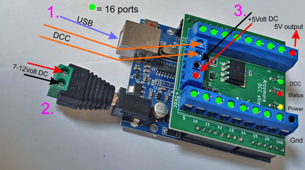
A DCC shield on top of an Arduino UNO or Arduino MEGA. (Arduino not included)
Can be powered:
– via USB
– Arduino jackplug 7-12 Volt
Screw-to-jack plug included!
– External 5V to screw terminal
Indicator leds for power, status and DCC
SMD print, only solder terminals and Dupont pins.
Price: €7,95
No longer available. Sold out!
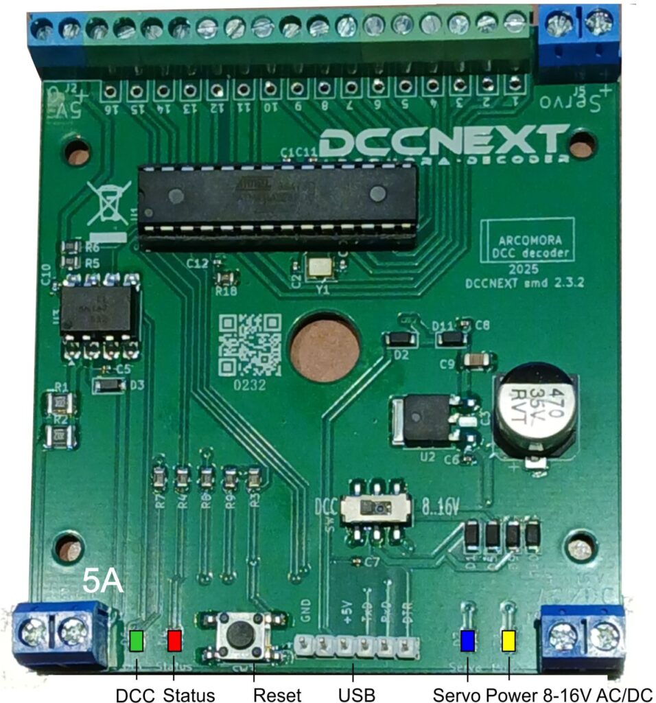
You can also use the DCCNext. The DCCNext combines an Arduino and the DCC shield on a single pcb. A separate Arduino is no longer required.
This is absolutely Genius, the Mardec is so easy to operate, even for electronic illiterates like me. Works like a charm. I definitely going to use the software and the shields to operate all servos on my layout.
Hi Peter,
Thanks for your kind words!!
Nico
Hello,
Looks like the perfect solution for me !!!!!
Question : can you link more DCC/Power boards so I can operate about 60 servo’s ???
Would be glad to hear from you.
Rudi.
Yes you can. For 60 servo’s you need 5 Arduino’s with DCC shields. Supply the DCC signal to all 5 shields
OK.
I will start with two UNO’s then.
Thnx for your reply.
can you help me with the source code in a .ino file?
After installation of the software the .ino file can be found in My Documents/Arcomora.
Hello.
Great job on this software.
Is it also possible to control motors, using a dual h bridge?
Thanks in advance
Filipe
No. Mardec is not designed for controlling motors.
But you can use an Arduino of course.
Hi again.
I am still a newbie on Arduino and the Mardec but I already got it working with an Uno.
Fantastic. Thanks for the software, it is very easy to use.
Now I also have a Nano that I would like to test.
I added a “new Arduino” on a different Com port and it was well detected. I tried loading and configuring Mardec on the Nano but it fails. It says on avrdude that arduino is “not in sync”.
Probably I need to select to upload to Nano instead of Uno, but how? Can you help me?
I know that the Nano is workling properly because I can upload sketches to it using IDE.
Thanks in advance.
Filipe Almeida
You need the Nano version of Mardec. In the installation folder. you will UploadNano.cmd. Use that to upload the nano version (Mardecn.hex)
Nico
Hello Nico !
I just tried to upload MardecN to a Nano-clone with ch340 chip.
After renaming MardecM to ..N AVRdude started to upload, but broke off with an ERROR: adress 0x8010 outof range …..
Any idea what went wrong?
PLEASE READ THE MANUAL!!!
To upload Mardec to a Nano you must use the Arduino IDE. However, the default boot loader is too large, which means
there is too little memory available for Mardec. However, you can replace the bootloader.
See the document ‘fixing the boot loader’ at http://www.arcomora.com/download/
Then you can use the IDE to upload the .INO file.
Nico
I know this will work with servos but will it also work with Tortoise type stall motors, please?
Cheers, ted
No it will not work with Tortoise type stall motors,
After a short look at stall motors I don’t think they can be controlled by an Arduino in the same way as servo’s.
The Mardec cannot control directly a Tortoise motor as servo, but with a 2 relay module and the Accessory Mode Single Steady, we can control the motor. The motor will be powered continuously, but that is not a problem, the motor will only draw 15-16 mA at stall.
I can’t add a schematic here, but you must apply 12V between pin 1 and pin 8 of the motor to let it turn in one direction and reverse the polarity to turn it in the other direction. With the 2 relais you can configure that.
Hi Nico,
Thanks for making this project available. I’ve built one of the DCC shields I ordered and I was wondering if you could steer me in the right direction on an issue I’m having? I’ve set up an Arduino UNO as my base station and use JMRI as my control programme. I’ve set up some relays (to control layout lighting) and a flickering led (welding simulation) via Mardec and it works fine through JMRI. I also set up a couple of servos (address 200 and 201) that test fine using Mardec but won’t work with JMRI or the base station command window. I believe it’s an issue with addressing and nothing at all to do with Mardec. I have tried several addressing combinations including sub-addresses, but to no avail. Any idea what addresses I should use to get this working. Please excuse my ignorance as I’ve only just started looking at DCC and JMRI and again, this issue is to with my ignorance and not your project.
This is really cool, also thanks for providing the code.
Are there any plans to modify the software to use all the pins on the MEGA2560
Not for the moment. Sorry
Nico, I too would like to utilize the Adriuno Mega. Would you consider such an update? In fact, at the current cost, a lot of people are migrating to the Mega as the standard. Currently, I just purchased 3 Megas for less than $3.00 more than I could have gotten the Unos. Also, possibly a video example of implementing more than one Arduino Mardec system would be of great value.
Thanks for listening,
Jim
Man this is awesome must have for Arduino and DCC geeks
Thanks for the efforts I was recommended by Rudi
I am able to run my servo and a led with this using Mardec and easily able to configure the address and Pins .I am using DCC++ as my Decoder and tried to run the servos using the commands as per documentation but I see no movement
I think my Breadboard for DDC signal with Optocoupler is working as I ran the DCC monitor and send commands from DCC++ and I was seeing the value DCC monitor.
Can you please advise if I am doing some thing wrong
Zou het mogelijk zijn om arloco te gebruiken met de okkie achter de oude rosoft s88? Dat deze met de ethernetkabel verbonden worden?
Je viens de tester “MARDEC” sur un ARDUINO UNO et celà fonctionne du premier coup. Bravo, c’est super à utiliser.
J’ai 2 questions:
– est ce que l’utilisation de l’EEPROM n’est pas limité en nombre d’écritures?
– pour l’installation dans un NANO, j’ai bien trouvé UploadNano.cmd, mais je ne vois pas comment l’utiliser. Si je clique dessus, rien ne se passe.
Un petit commentaire: dans votre documentation, vous parler de “point de grenouille”, je pense que la traduction française exacte est : “pointe de coeur” pour un aiguillage.
Cordialement
I will fix the French document.
Yes the EEPROM has a limited number of writes. But that is very big.
But Mardec uses EEPROm.Update commands instead.
Use the Upload tool in the Start menu. But the Nano requires first a new boorloader.
See manual.
Hello,
I just tested “MARDEC”, and it works the first time.
Very good job. It’s very friendly to use.
I have two questions:
– I suppose, you are using EEPROM to keep the position of the servo.
Is there a maximum times of writing in EEPROM?
– I wish to load the software in an ARDUINO NANO. I have found the “UploadNano.cmd”, but when I click on this file, nothing happens.
What is the good handling?
Just a little thing in the French translation: you talk about “point de grenouille”, the best traduction in French is “pointe de coeur”.
Regards
Hi Nico.
I have build several DCC / Power boards now and all are tested via a laptop computer and I must say that they work like a charm (with the computer connected).
But now comes the problem, when I connect the Arduino (with the DCC / Power Board) to the DCC of my train layout instead of the computer, the servo will not react.
I have a Z21 (the black box with white router) but I do not understand how to go further so that the two systems communicate.
Maybe a clear instruction sheet could be added to your MARDEC manual. I know it should work, but i am not such a bright light in this matter.
Can you please help me out ( or somebody else perhaps who has already his turnouts operated by servo’s and MARDEC).
With my best regards,
Roel Lambrechts.
Did you switch to normal mode?
Did you configure the address offset for the z21?
This is a really great package. It took just a bit of getting in to, and Nico was extremely helpful. Mainly lack of familiarity with DCC slowed me down, once I got to grips with it, it was so easy to set up accessory ports, change parameters and add functions.
By comparison, I have a DR4024 which was tricky to set up and did some strange things. I wish I’d found Mardec first.
Hi Nico,
I live in the middle of Germany and I must give you my congratulations for those marvellous programs.
I use Mardec and Arsigdec and in the meantime I´ve build more than 20decoders which all work fantasticly.
Thank you for you help.
Best regards
Carl Jaeger
On the double shot mode can you limit the time in the high state?
On Kato turnouts you need to apply 12v with the polarity in one direction to switch the point and to return you need the opposite polarity.
However you must not leave the 12V on or the motor overheats.
About 250mS is as long as the 12V needs to be active.
I expect to use a H bridge driver to actually switch the 12v as I don’t think the DCC next will switch it.
So one output will be connected to enable on one half of the H- bridge and the other to the enable on the other half of the H-bridge.
I have tested this on an arduino and it works but I don’t have the DCC interface.
Hi Dennis,
Yes you can specify the length of both ‘shots’.
Have a look at the third video on the VIDEO’S menu.
For the DCC interface you can order a DCC shield or the DCCNext.
Nico
I use the Double one shot and a L9110S DC Motor Drive Module to control the Kato turnout. with a pulse of 300 ms.
Hallo Nico,
Is het mogelijk om een geprogrameerde “mardec” weer uit te lezen naar de PC? Laden gaat uitstekend en de werking is prima. Maar is omgekeerd ook mogelijk?
m.vr.gr. Henk Schipper
Waarom zou je dat willen?
De source (Mardec.ino) staat, na installatie van de software, gewoon op je PC (MyDocuments/Arcomora).
En als dat niet zo zou zijn, kun je beter gewoon vragen om de source.
Want ‘uitlezen’ kan echt niet voor zover ik weet.
Nico
Hi Nico
is it possible to change the frogpoint polarization from a normal to a (double coil) bistable relay (using two outputs)? Some turnouts stay in the same position for hours and I don’t want to have my relay coils powered for such a long time, so it would be perfect to use a bistable relay and switch the polarization with one single shot.
Hi Roger,
1) you can switch the wires on the relay to enforce that the most used postion is not energized. So if a turnout is 90% of the time straight then the relay is only 10% of the time energized.
2) With Mardec 5.1 you can connect the frogport to an input port. Configure the input port with trigger option ‘Level’.
On a third port you configure a ‘one shot’ accessory with the same DCC address as the input port.
Example (Mardec 5.2 beta)
Port 1: DCC 1, Servo , Angles 75/105, Not Inv., Speed 25, Frog port 16, Bounce (L/H): 0/0
Port 2: DCC 2, Input , Trigger: B, Second addr/delay: none, Third addr/delay: none
Port 3: DCC 2, Acc.type 5 (S. One shot), , Not Inv., Time(ms) 200, Trigger: B
Port 16: First relay (No inv.) for port 1
Connect port 16 to port 2.
If the frogport (16)changes, forced by address 1, the input port (2) is triggered and because the ‘one shot’ on port 3 has the same address, the ‘one shot’ fires a pulse.
Address 2 is not used as a DCC address in this situation.
Nico
Correction:
To fire a ‘one shot’ on both flanks you require Mardec 5.2 beta
Nico
Hi Nico
your suggestions showed me to another possible solution: As I need a separate board using MOSFETs to power the (bistable) relays I could try to integrate a small logic circuit which fires a one-shot on one port on change of the input from 0 to 1 and another one on the second port on change of the input from 1 to 0 (I don’t know yet how to realize this). So it should be possible to use the “normal” relay output for switching a bistable relay.
Hi Nico, you did a great job. I’d like ti know if is possibile configure mardec in a MacOS system using something like putty.
Thanks,
Andrea
Hi Andrea,
You can install a MacOS version for Putty:
http://macappstore.org/putty/
or
https://www.puttygen.com/download-putty
You must also use the Arduino IDE for uploading the .ino file
You may also need the CH340 drivers for MacOS
They are part of Arcomora software installation.
Nico
Hi Nico, I found macOS Version of putty, now I have another question.
I’d like to upload Mardec on an Arduino Nano, and I know I had to use the upload tool and the mardecn.hex file.
I need to use pin 3 for Dcc input instead pin 2 (it’s a long story…), so I had to change DccInterrupt from 0 to 1 and change the number of the input pin, but I found only a generic mardec.ino file in my ducuments folder, can I use this file (modified) or I need a specific nano sketch?
Thanks,
Andrea
There is no specific nano sketch. At compile time you must specify for which Arduino you want to compile. That results in different hex-files for different boards.
So you must make your changes in Mardec.ino and then compile it for a Nano.
You also need the DCC_Decoder library from Mynabay.
Nico
There is no specific nano sketch. At compile time you must specify for which Arduino you want to compile. That results in different hex-files for different boards.
So you must make your changes in Mardec.ino and then compile it for a Nano.
You also need the DCC_Decoder library from Mynabay.
Nico
Perfect, I’ll try as soon as possible.
Thank you.
A.
Hi Nico,
very interesting and helpful for me. Just one question: Is it also possible to control e.g. a servo manually with connected push-buttons?
Best regards,
Axel
Hi Axel,
Yes, you can control a servo or accessory by both DCC and manual with push buttons.
Nico
Hi Nico,
I have built a DCCNext module. It works well, except that when resetting it, via the button or by switching the power off-on, the DCCNext restarts in configuration mode, not in run mode. So that it is not possible to use it without a connection to the PC.
Philippe
Hi Philippe,
Have a look at the manual.
Search for the I-command to change some initial settings.
One of them is the startup mode:
– Choose how you want Mardec to start up: As ‘last mode’, always in configuration mode or always in normal mode.
Hi Nico, thank you very much for your fast answer. I had overlooked this command. I’m preparing a memo for our club (AMFB in Belgium) and I hope that DCCNext will be adopted for the extension of our club’s layout.
Philippe
Beste Nico
Er is een nieuwe arduino uitgekomen te weten de NANO Every.
Als ik Mardec upload naar deze arduino krijg ik een sync fout.
Ik gebruik liever geen kloon in verband met de betrouwbaarheid hiervan.
Een originele NANO Every kost maar 8 Euro
Is er een mogenlijkheid om deze alsnog te gebruiken?
Als je intresse hebt wil ik wel 5 stuks doneren.
Met Vriendelijke Groet: Rob Blaauw
Logisch dat je een sync fout krijgt. Bij de upload moet het board type worden opgegeven en de Arcomora scripts kennen de Every niet.
Even gegoogeld op de Nano Every.
To mijn verbazing zag ik dat er slechts 256 byte EEPROM in zit.
Dat gaat niet werken met de Arcomora sketches.
In de gewone Nano en Uno zit 1024 byte en de Mega 4096 byte.
Beste Nico
Dank je wel voor deze info.
Dan zal ik binnenkort een aantal bouwpakketen bij Arcomora bestellen.
Met Vriendelijke Groet: Rob Blaauw
Hi Nico,
Got my servo working using Mardec 5.1 on an Uno. The only difficulty I had was the Servo (SG92R) jittered but this was solved by connecting the Uno ground to the servo ground. It’s all good now.
Thanks, Ted
Hallo Nico,
vielen Dank für MARDEC, ist einfach zu bedienen mit vielen Einstellmöglichkeiten.
Ich benutze Mardec mit mittlerweile 6 Arduino als Decoder für meine Modellbahn schon seit 2017, alle funktionieren fantastisch.
Meine jetziges Projekt wird ein Kran mit vielen Funktionen mit Mardec gesteuert.
Dafür benötige ich für die Krandrehungen ein Servo welches mindestens 4 verschiedene Stellwinkel ansteuern kann. Vielleicht können Sie mir mitteilen
ob dies mit Mardec ausführbar ist, und wenn ja, wie.
Danke für die Hilfe.
Freundliche Grüße
Hallo Wilhelm,
No that is not possible. The basic idea of Mardec is that a servo can have only two angles.
But you can always program it yourself.
Nico
Dag Nico,
Wanneer ik de spanning op de baan zet gaat de DCC-Next in de programmeer modus.
(rode led knippert 3 maal en blijft dan branden)
Ik krijg hem daar alleen weer uit door deze via de USB kabel in de bedrijfstoestand te zetten.
De DCC-Next wordt gevoedt met de voeding voor de servo’s en de jumper staat op servo
Hallo Jan,
Wordt de servo voeding tegelijk aangezet met de baanspanning?
Zo ja, pas dan de opstartmodus van Mardec aan met het I-commando.
Nico
Ja, dat is het geval.
Bedankt, ga ik de opstartmodus wijzigen
Voor het overige draait het als een tol, de baandetectie doe ik met Arloco en dat gaat ook prima, mooi materiaal en een goede begeleiding lees ik uit de beantwoording van alle vragen “hier boven”.
m.v.g. Jan Koelewijn
Hello Nico,
Assembly and beginning worked well. Great praise for the development.
I want to control several servos on a switch route, but not at the same time. Can i program a break in between.
mfG Günther Haas
Hi Günther,
Mardec can’t do that. The servo starts rotating immediately after its DCC address is received. But perhaps you can control it in your train control program. Most programs has an option to add a delay before sending the address.
Nico
Hi!
I love your DCC-next. Perfect product. But I have one issue. And I don’t know if the problem lies in my commandstation (Lenz) or in the DCC-next.
The problem is that I need to send multiple repeted commands from the throttle for a servo to react.
If i connect a switch to an input the corresponding servo reacts imediatly.
I dont have an other commandtstion to test with. Have you had any issues with the Lenz system?
Hi Karl-Fredrik,
I have no experience with the Lenz system.
But you can verify the correct sending of addresses with the DCCmonitor.
It is part of Arcomora. You can upload it with the Upload tool.
Nico
Hi Nico,
thanks for your great work!
In the manuals and I think also on the webpages, you indicate that a separate optocoupler circuit is needed to connect the arduino / shield with the DCC signal. But on your shield, there is an 6N137. Do we really need an additional optocoupler circuit?
Thanks and best regards,
Andreas
Hi Andreas,
Misunderstanding.
You need:
– An Arduino + home made DCC circuit as shown in manual
OR
– An Arduino + DCC/Power shield (shield includes DCC circuit)
OR
– A DCCnext decoder
AND the free software.
Nico
Hi, great job on arduino uno. My question is how to load “mardec” on the Atmel Mega 328p nano.
I am at the basics it is a week that I am playing with it. I have read, but cannot find the “mardecn.hex” file.
I am very grateful to you and thank you in advance for your explanation.
Sorry for my English
Best regards Roberto
Hi Roberto,
There is no MardecN.hex
How to use a Nano is described in the manual.
Quote from manual.
To upload Mardec to a Nano you must use the Arduino IDE. However, the default boot loader is too large, which means there is too little memory available for Mardec. However, you can replace the bootloader.
See the document ‘fixing the boot loader’ at https://www.arcomora.com/download/
Then you can use the IDE to upload the .INO file.
Hi Nico,
thanks for the reply, now everything works.
Good job. Thank you for your interest.
Salerno (IT) greets you.
Roberto
Hi Nico, thank you again for this great project!!
I have a small suggestion for improvement. I am using a arduino uno from az-delivery which is recognized as an “USB Serial Port (COMxx)” device in my Windows10 system. In this case the upload tool does not work, it always says “No port available”. So i added the following line in the NewUpload.vbs file in the function “AskPort” below line 151:
If InStr(portinfo.name, “USB”) 0 Then Allport=Allport+VbCrLf+portinfo.Name
then it worked with my arduino.
Thank you again!
Regards Frederik
Hi Frederik,
A device “USB Serial Port (COMxx)” is probably not a unique name. I assume there may be more devices with this name that are no Arduino’s.
It is a very generic name. So I’m not sure I will do this.
But what drivers are using? CH340 or Arduino original?
Nico
Good morning Nico, once the DCCNext kit is assembled, I have installed mardecpin software, and I have connected: everything ok.
Then I have installed a servo on port 1 and configured with Mardec. I have connected dcc signal and 5V servo power supply, SERVO jumper on PCB and everything ok: the servo responds in its dcc direction ..
I connect a second servo to port 2, I configure it anyway and nothing works anymore.
Port 1 stops working.
I have reinstalled mardecpin in the DCCNext, and now ports 3 to 19 appear, and 3 cannot be configured, the others do not work.
Any guidance?
Why oh why do you upload Mardecpin to a DCCNext?
Did you read the text on the download page?
No DCCshield or DCCNext?
It may easier to use the pin-version of Mardec 6. This version uses the physical pin numbers of the Arduino instead of the port numbers 1-16.
The DCCNext uses port numbers 1-16!
Hi Nico,
sorry for my clumsiness. Perhaps the translation has played a trick on me. So what software should be uploaded to DCCNext?
Or maybe, the chip was programmed in the kit?
What I can do?
a greeting
I think I already know how to do it. Mardec is loaded from a shortcut of Arcomora software, I’ll confirm if I get it.
The initial problem I had is that I could not install arcomora software in Windiws XP (I usually work with Mac, and I only have a couple of computers with XP. They left me another PC with Windows 10, where I could install arcomora.
Hello Nico
Amazing work with the Mardec firmware, love the simple programming via Putty.
I have been experimenting with Railcom on my ECoS and have noticed that my home made dcc shield/Nano units have some problems with reliability ie not switching points every time. Once Railcom is disabled everything is fine, your DCC power shield/ UNO combination seams unaffected by the Railcom signal? Have you any experience with Railcom problems ? I will replace my Home made DCC shield with your design as my one is based on Geoff Bunza’s circuit. Hopefully that will get the Nano unit back up to 100% reliability.
Hi Martin
Thanks for your compliments.
In the manual it is advised to turn off Railcom.
Some users noticed indeed problems with Railcom and advised me to turn it off.
I added that to the manual.
I have no experience with Railcom myself.
Nico
Hi Nico,
It is strongly adviced to use a separated 5v power for servo’s.
I Have many 5 v 2 Amp’s power supply’ s used to charge mobile’s, tablet etc.
Will they also work as power supply for servo’s?
Grtz P.Kramer
Hi P. Kramer
I would not trust the 2 Amp. A charging device is not designed as a Power supply.
I don’t advise it.
But an old laptop power supply can be used.
Nico
Nico,
Maybe you know the problem using Peco N Points. The power of the frog should be supplied seperately with a relay switch. But this has to be done at the right moment to prefent shortcircuit. Namelly exactly halve way the switching movement. The construction of the servo must be precise to accomplish that.
A more save way is to use 2 relay and activate them in this oder.
Disactivated relay 1 ( No power on the frog) – make the switch – activated relay 2. (restore power to the frog)
This is mainly a problem bij the Peco N points with electrofrog. (only 3 mm movement)
Do you understand the problem and is there away to do this with a mardec or DCCnext solution?
I understand the problem and Mardec is a perfect solution for it.
Have a look in the Mardec manual for the F(rog)-command for servo’s.
Both solutions (1 or 2 relays) are available.
Nico
First of all a complement for the good design & easy to use software.
I do have a question about the PWM though; the standard frequency is 800Hz i believe? Is there a way to modify that? I’ve been trying to control the speed for some motors (magnorail) of the boards, which works ok. The only downside is the noise the pwm causes, especially at low rotation speeds. I wonder if changing the frequency could help that.
And a though for aditional functionality;
It would also be very nice if it where possible to control the pwm like you would control a train normaly, so not just on/off but use the speed of a loc-adress.
Ofcourse a normal loc decoder could be used, but that would have to be powered of the track, since they have no seperate power input. Also would be very expensive to use a loc-decoder with lots of extra boosters just to control scenery.
Hi Ashley,
I must confess that I’m not a Arduino ‘inside’ specialist.
So I can’t really answer your question. But I guess it is not possible; at least not in a simple by software setting.
Theoretically your suggestion is possible. At this moment Mardec controls only accessory addresses.
DCC monitors reads both loc and accessory addresses.
Though you could implement that in Mardec and use only the locspeed (28 steps) data for controlling the PWM output.
But Mardec has already reached its maximum memory size. It is not possible to add more functionality.
Nico
Hello Nico,
I receive the package, thank you for the invoice and the great job.
I have a question related to Mardec to command solenoids.
I see 2 diodes 1n4148 after the Mosfets.
Could you explain the purpose ? I will die less stupid…
Philippe
It is a so called suppression diode.
If a current flows through a coil, it will generate a counter-emission. This will cause a current to flow in the opposite direction. If no diode is placed, the coil may start to oscillate. This can also cause high voltage peaks and the diode also provides protection for the transistor controlling the coil.
Hi Nico, I had a look at your program with the mardec code and I muist say, I am impressed.
I use DCC++, so not exactly your concept; a friend of mine introduced you and I am having some looks at your designs. Very nice work.
And I really do appreciate you publish your code, congratulations.
Hi Erik,
You can use Mardec also with DCC++. There are many DCC++ users that also use Mardec.
Nico
I am looking to control the doors on my engine sheds, I have 15 of them, I would like to operate them with servos that are adjustable on the angle and I would like to have an led that flashes blinks when the servos are operating, is this something you equipment is capable of? If so can you please advise what is required to do this.
Yes. Mardec can do that job.
Port 1 configure servo (DCC 100)
Port 2 configure flashing led (Accessory mode 3; DCC 101)
Port 3 configure ‘one shot’ with time t. (DCC 100)
Port 4 configure Input type: ‘B’ with DCC 101.
Connect port 4 to port 2
When DCC 100 is send:
– servo starts rotating (DCC 100)
– one shot starts (DCC 101) –> Led starts flashing
– After time t one shot ends and will stop flashing
Measure the time t for closing/opening the door
So each shed requires 4 ports. In total for 15 sheds 4x DCCNext (or DCC shield)
That is the duration of the one shot.
See Mardec manual for fully understanding on how it works.
Nico
Hi Nico
I have a number of Mardecs in use and all are working 100%. I now want to add a couple more and would like to make use of the Mardecpin software.
Question : How do I load it?
Hi,
You can download it from my downloadpage.
Nico
Hi Nico
Sorry I meant how do I load it into Mardec?
Ah. Sorry. First of all: you do not load into Mardec but upload Mardec on Arduino UNO.
Upload .ino file: Install the normal package and the Arduino IDE. Open .ino file in the IDE and compile and upload.
OR
Upload .hex file: Install the normal package. Copy the Mardecpin.hex over Mardec.hex.
Use upload tool for uploading to Arduino UNO.
Nico
Got it thanks.
Gareth
I just wanted to say a big thank you to Nico for allowing us to purchase these kits and build them at such a cheap price.
I bought a couple of kits (ArLoco, DCCNext and a couple of Okie8’s) probably about a year ago, but I have only just seriously started exploring it all now I have a bit more time and these are as good, if not better, than a lot of commercial products. I am using a DCC++EX controller and JMRI and it just works flawlessly.
Thanks again!
Hi Brendan,
Thanks for your kind words
Nico
Hi Nico, big compliments for the design and publication of the software packages. I have one issue running Mardec on UNO : the speed setting of the connected servo at port 5,6,7,8 does not have any visible effect. The servo are operating at 5V and moving from aprox. 60 to 120 degrees.
Do you have suggestion how I can adapt the speed ( slower).
Best regards Rens
Hi Rens,
Did you read the manual?
There you can find the S-command to set the speed.
When in config mode use the C-command for testing the speed
Nico
Hi Nico, yes I am using the S command, but does not have any visible effect . I have tried minimum value of 5 ms/degree , the default of 25 and the maximum of 100. The values are shown in the Document command, but visible no effect.
Nico, sorry for the confusion. I used the T command for testing. Indeed the Change command works. Thanks!
This is a Google translation
Hello,
I’m just doing a dry run because I’m missing the optocoupler. But this is not necessary to test the software. (Only on the PC)
So connected the servo to UNO and started the software. Unfortunately, the servo doesn’t move a bit.
Is there a translation table for the PIN code? The software speaks of port 1-16, but the Adruino has 0-13 (IDE)+18-19 and A0-A5 (analog).
Found a pinout diagram where there are port pins but they are called PD0-PD7 and PB0 to PB5 and PC0 to PC5.
Presumably it’s IDE or physical pin arrangement?
Chris
Hallo,
bin grad bei einer Trockenübung, da mir der Optokoppler fehlt. Aber zum Testen der Software ist dieser ja auch nicht nötig.(nur am PC)
Also Servo an UNO angeschlossen und Software gestartet. Leider bewegt sich der Servo kein Stück.
Gibt es eine Übersetzung Tabelle für die PIN Belgung? In der Software wird von Port 1-16 gesprochen, der Adruino hat aber 0-13 (IDE)+18-19 und A0-A5(Analog).
Hab ein Pinout-Diagram gefunden wo es Port-Pins gibt aber die heißen PD0-PD7 und PB0 bis PB5 und PC0 bis PC5.
Vermutlich ist es IDE oder Physical Pin Anordnung?
Chris
Hi Chris,
Have a look in the Mardec manual. There you can find a conversion table.
You can also order a DCC-shield. That also uses port numbers 1 to 16.
Much easier.
Nico
Hello,
I’m using Mardec and ArLoCo and I’m very satisfied.
I have 3 ArLoCO and OKKIES and 5 Mardec.
Now, I’m need a decoder like Mardec, with 48 Output, for a TCO.
Is it possible with Mardec and a MEGA2560 to have 48 output, like with ArLoCo
Regards
Hi Pierre,
No, that is not possible. Sorry
Mardec supports only 16 ports for an UNO or DCCNext.
The DCC-shield can be placed on a MEGA but still with only 16 ports.
So you need 3 DCCNext or 3 DCC-shields-with- Arduino.
Hello Everyone,
Just want to leave my testimony to the great products (HW + SW) developed by Nico Teering.
I start using them some months ago and although there were some issues at the beggining, mostly motivated by my eagerness to put the decoders to work and not paying enough attention to detail (i.e., not reading the manual in full detail…), I have to say that everything is working smoothly and these are, no doubt, great products and for a really very economical price. I have now Loconet Arduino shields for my current sensors, which are based on Okkies and also DCCNEXT decoders for the servo and signal control, everything running with Rocrail through a CS2.
One big thanks as well for the great support (and patience) of Nico Teering. Cannot say how many times I bothered him with issues and always got the right answer and solution for the problem.
I still have a way to go to complete the automation of my layout, but I’m truly confident that with ArCoMoRa it will be an easy task.
Thanks!
All the best,
António
Hi Antonio,
Thanks for your kind words
Subject: DCC/Power Shield
Hello Nico,
First of all, thank you for your perfect modules, which I already have in use.
In the construction manual for the DCC/Power Shield there are 2 options for the implementation. Is it possible to solder all the components that are included and then choose between the two options?
Thanks in advance for your efforts.
Kind regards
Reiner
Hi Reiner,
Yes you can still use option 1 (power by jackplug on Arduino) while all components are already soldered.
But don’t also connect power to the screw terminals on the shield!
Nico
Hi every body
I’m testing the Mardec program. It seems to be fantastic !
I want use it for driving servo’s
On testing all is OK and the DCC monitor read the signal
But I don’t arrive to command the servo with my DCC station (Intellibox IR)
Please, somebody can help me ?
Alain
Hi,
Did you switch over to Normal mode by entering the E-command?
The red statusled must be off then.
If you did so, then it may be that the optocoupler 6N137 is failing
The green DCC-led must be on when DCC is connected.
Try switching it with another DCCNext (if you have)
Nico
I use MTB point motors. Can MARDEC be used to switch these MTB point moters?
Is it done with Mosfet? Can you please explain how it is done with Mardec.
Thanks
William
Hi William.
I have no knowledge of these motors but I assume you can control them as described in the Mardec manual.
Use accessory mode 6 (double one shot) and an MOSFET unit as described in the manual.
But no guarantee as I have no knowledge of these motors.
Nico
Do you think 1 Mosfet is ok or do I need 2 mosfets as my MTB point motors need 3 wires
Thanks
William
You need two as shown in Mardec manual
I have build my first MarDec and am testing with DR60030 servo’s. but to me there seems to be no difference if I use the fastest or the slowest speed on the servo.
Is this expected behaviour?
Settings of MARDEC #1
Default servo rotation speed: 100 ms/degree
Address offset: No
Servo’s are detached at end of rotation
Startup mode: Last
Port 1: DCC 201, Servo W11R, Not Inv., Angles 5/175, Speed 100, Frog port 9, Bounce (L/H): 7531/7531
Port 2: not configured
Port 3: not configured
Port 4: not configured
Port 5: not configured
Port 6: not configured
Port 7: not configured
Port 8: not configured
Port 9: First relay (No inv.) for port 1
Port 10: not configured
Port 11: not configured
Port 12: not configured
Port 13: not configured
Port 14: not configured
Port 15: not configured
Port 16: not configured
I would expect it to take 17 seconds (175-5=170degrees @ 100ms/degree) to make a full switch.
Did I miss anything in the manual?
How did you test? With the T-command? You must use the C-Command.
In normal mode the speed will also be OK.
Nico
I have the following problem. I have done the fixing a bootloader without any error.
When I try to upload Mardec to my Nano I get following error:
avrdude.exe: verifying …
avrdude.exe: verification error, first mismatch at byte 0x7800
0xff != 0x0e
avrdude.exe: verification error; content mismatch
avrdude.exe: safemode: Fuses OK (E:00, H:00, L:00)
What I am doing wrong?
I also tgried to upload the hex file to the nano with AVRDUDESS but I get the same error.
Please your reply.
Thanks in advance.
William
Nico,
In initial setup, I choose the start in normal mode. Yet it always reverts to start in last mode..
That in turn is un-requested programming mode.(on occasion).
How can I enforce normal start mode?
Hello Nico,
Can you confirm when the PowerNext-P module will be available ?
Very interesting interface.
Best regards,
Alain
Hi Alain,
The PowerNext-P is not yet available.
But you can order it again.
Nico
Hi Nico
Will you develop a servo card but with Loconet instaed of DCC?
Would be nice to control servo thru loconet bus.
You refer to ASAR but that i s totaly manual with switches.
Can we incorporate the loconet plug to the unit?
After years of puzzling over how to create a hassle-free control system, I finally found the solution.
ArCoMoRa!
After just an evening of reading manuals and a late afternoon of soldering, I have 4 signals and 5 turnouts up and running.
Too bad Nico I hadn’t spot you sooner, but you pulled me out of a rut.
Thanks a bunch!